100 Amp Subpanel Wire Size: Copper vs. Aluminum (DIY Guide)
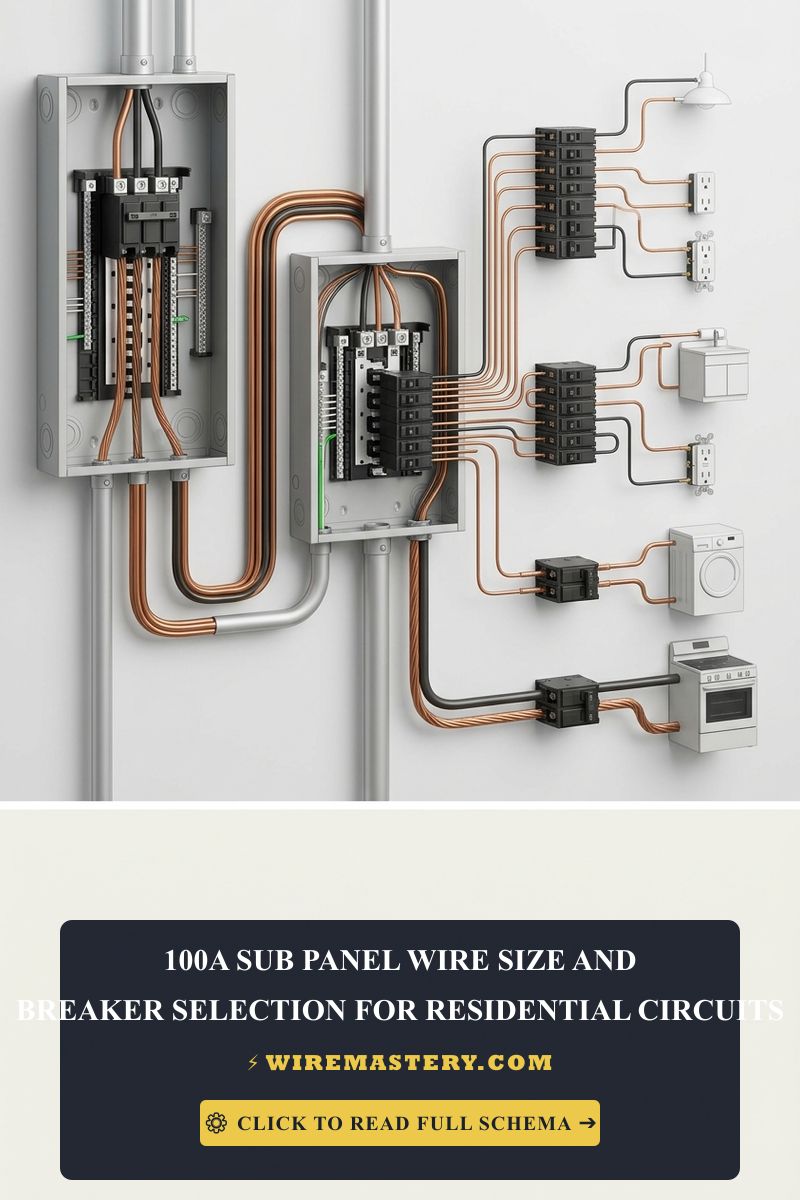
When expanding your home’s electrical infrastructure to accommodate heavy modern loads—such as centralized HVAC installations, multi-zone kitchen remodels, or dedicated subpanel hubs—adding a secondary distribution node is the standard operational procedure. Implementing a 100A subpanel optimizes multi-circuit branch management and prevents your main service panel from crowding. However, securing full building safety demands absolute mathematical precision when calculating feeder thickness.
The exact 100A subpanel wire sizes, mandatory voltage drop gauge corrections, and National Electrical Code (NEC) separation parameters engineered for residential grids.
Core Subpanel Sizing Benchmarks
Before running feeder lines through your property’s interior framing, establish your structural load baselines:
- Continuous Load Thresholds: Branch feeds must be calculated to handle 100% of non-continuous loads plus 125% of continuous loads (circuits operating for 3 hours or more) under standard NEC metrics.
- Terminal Limitations: Residential 100-amp circuit breakers utilize lug blocks calibrated for 75°C insulation limits. Calculations must strictly follow this column profile to prevent thermal degradation at the termination point.
- Enclosure Clearance: Subpanel installations must maintain a minimum clear working space of 30 inches wide, 36 inches deep, and 6.5 feet high in front of the cabinet framework under safety rules.
Technical Materials and Subpanel Tools Checklist
Manipulating heavy multi-conductor feeder lines inside a residential enclosure requires specialized insulated tools to ensure low-resistance contact mapping:
| Panel Installation Tool | Primary Technical Purpose |
|---|---|
| Ratcheting Cable Cutters | Provides the mechanical advantage required to cut through thick #3 AWG to 1/0 stranded lines without crushing. |
| 1000V Insulated Screwdrivers | For torqueing breaker terminals and neutral bar set-screws without slipping risks. |
| Digital Clamp Multimeter | Measures real-time current balancing across both hot phases to diagnose voltage drop conditions. |
| Calibrated Torque Wrench | Code-mandated tool to verify that all panel box lugs are tightened to exact manufacturer inch-pound footprints. |
Sizing the 100A Feeder Run: Sane Conductor Matrices
To ensure full code compliance, you must select your wire cross-section based on both the conductor material composition and the physical length of the structural run. Sizing must follow NEC Table 310.16 to accommodate proper thermal heat dissipation inside wall cavities.
1. Standard Runs up to 100 Feet (The Base Profile)
For standard interior installations running short paths through structural studs, stick to the baseline ampacity thresholds:
- Stranded Copper Option: Requires a minimum of #3 AWG copper wire (THHN or THWN-2 insulation profiles).
- Stranded Aluminum Option: Requires a minimum of #1 AWG aluminum wire or copper-clad aluminum equivalent.
2. Long-Distance Voltage Drop Corrections (Detached Garages & Workshops)
The internal resistance of long wire lines causes voltage drop over distance. When routing a 100A feeder run to a detached garage, backyard workshop, or outbuilding extending past 100 feet, you must upscale your wire size to keep total voltage drops below the 3% target recommended by the NEC:
- Stranded Copper Long Run: Step up from #3 AWG to a minimum of #2 AWG copper wire.
- Stranded Aluminum Long Run: Step up from #1 AWG to a minimum of 1/0 AWG (One-Zero) aluminum wire.
Official 100A Subpanel Sizing and Length Reference
| Conductor Material | Short Run (0 - 100 Ft) | Long Run (100 - 150 Ft) | Conduit Fill Metric (PVC 40) |
|---|---|---|---|
| Stranded Copper | #3 AWG | #2 AWG | Minimum 1.25-Inch |
| Stranded Aluminum | #1 AWG | 1/0 AWG | Minimum 1.50-Inch |
🚨 CRITICAL SAFETY ENFORCEMENT: Isolate Ground and Neutral Bars Unlike your property’s main service panel entrance where grounds and neutrals bond onto the same metal bars, you must completely separate the ground and neutral bar systems inside every residential subpanel. Remove the factory green bonding screw or metal jumper strap from the subpanel neutral block frame. If you fail to separate them, normal neutral return current loops will pass down the safety grounding wires, electrifying the metal casings of your home appliances and creating live shock hazards across the building.
Downstream Breaker Integration Blueprint
Once your main 100-amp double-pole feeder breaker is snapped onto the primary panel bus bar and routed through your conduit, the subpanel interior will distribute energy through specialized branch breakers:
- General Receptacles and Lighting: Standard 15A or 20A single-pole breakers using 14 AWG or 12 AWG Romex respectively.
- Arc-Fault (AFCI) Protections: Mandatory under modern residential rules for bedrooms, living rooms, and family common areas to shield against hidden spark arcs behind drywall.
- Ground-Fault (GFCI) Protections: Required for wet zones (kitchen counter areas, bathrooms, garages, laundry nodes) to provide instant safety trip capabilities.
- High-Voltage Apparent Loads: Double-pole 30A to 50A breakers to feed heavy-duty dual-phase home machinery (central heat pumps, electric dryers, EV charging stations).
NEC Compliance & Official Safety Standards
Adhering to strict electrical installation codes protects your property value and ensures full insurance compliance. The National Electrical Code strictly regulates residential subpanel layouts, feeder counts, and terminal torque ratings under NEC Article 215 (Feeders), Article 250 (Grounding and Bonding), and the thermal tables of Article 310. Non-compliance can result in immediate inspection failures or absolute denial of coverage during a thermal emergency claim.
For current NFPA 70 guidance on 100A feeder sizing, conductor dimensions, grounding, and subpanel installation, consult the Official NFPA 70: National Electrical Code (NEC).







