20-Amp Circuit Breaker Wiring: Gauge & Installation Protocols
Upgrading or adding a 20-amp branch circuit is one of the most common and high-yield infrastructure improvements in residential electrical engineering. Standard 20-amp nodes supply the robust current pathways required for modern high-draw zones, including kitchen small appliances, laundry stations, and home workshops. However, working inside a live service panel demands absolute adherence to safety protocols and precise hardware sizing to avoid severe arc-flash hazards.
The exact wire gauge metrics, single-pole installation workflows, and National Electrical Code (NEC) boundaries required to wire a 20-amp circuit breaker safely.
Core Circuit Engineering Thresholds
Before snapping a new overcurrent protection device into your distribution bus bar, verify these core electrical metrics:
- Voltage Architecture: Standard residential branch circuits operate on a single-phase 120V AC timeline (requiring a single-pole breaker space).
- Conductor Constraint: The NEC dictates a strict minimum cross-section profile for 20-amp paths; utilizing small conductor profiles violates federal fire codes.
- Breaker Compatibility: Replacement breakers must match the official physical footprint and regulatory listing (UL) of your specific panel manufacturer (e.g., Square D, Eaton, Siemens).
Technical Materials and Panel Tools Checklist
Working inside an electrical enclosure box requires specialized trade equipment designed to isolate high-voltage currents safely:
| Panel Installation Tool | Primary Technical Purpose |
|---|---|
| Insulated Lineman Pliers | Rated up to 1000V to cut, pull, and accordion-fold thick copper branch conductors. |
| 1000V Insulated Screwdrivers | For torqueing terminal lugs, neutral bars, and breaker terminal screws without slipping. |
| Non-Contact Voltage Detector | Audibly verifies that panel bus bars and interior spaces are fully dead before trade work. |
| Digital Clamp Multimeter | To measure real-time circuit current draw and diagnose active branch voltage drops. |
Wire Gauge Selection & Ampacity Limits for 20-Amp Branches
Selecting the appropriate conductor thickness prevents internal resistance heat accumulation inside your walls. The National Electrical Code strictly regulates conductor profiles based on thermal performance under NEC Article 310.16:
Conductor Material Specifications
- Solid Copper (Standard): Requires a minimum of 12 AWG (American Wire Gauge). This is the industry benchmark for standard residential Romex configurations (Yellow sheath jacket).
- Solid Aluminum: Requires a minimum of 10 AWG. Due to aluminum’s higher internal resistance and lower conductivity coefficients, you must step up the gauge size to match copper’s thermal thresholds safely.
General Conductor Ampacity Matrix (Copper)
| Conductor Diameter (AWG) | Standard Romex Jacket Color | Maximum Overcurrent Rating | Primary Home Deployment |
|---|---|---|---|
| 14 AWG | White | 15 Amps | Low-draw lighting loops and bedroom outlets. |
| 12 AWG | Yellow | 20 Amps | Kitchen small appliances, laundry, and bathroom nodes. |
| 10 AWG | Orange | 30 Amps | Central AC units, water heaters, clothes dryers. |
Step-by-Step 20-Amp Circuit Breaker Installation Manual
1. Main Isolation and Enclosure Box Assessment
Locate your property’s main service distribution panel. Wear your rubber safety gear and ANSI-rated glasses. Turn off the main service disconnect breaker (usually a massive 100-amp to 200-amp switch at the top or bottom of the panel). Remove the outer panel deadfront cover plates. Pass your non-contact voltage tester around all secondary breaker terminals to confirm the entire load bus bar cluster is completely de-energized.
2. Splicing and Routing the Branch Cable
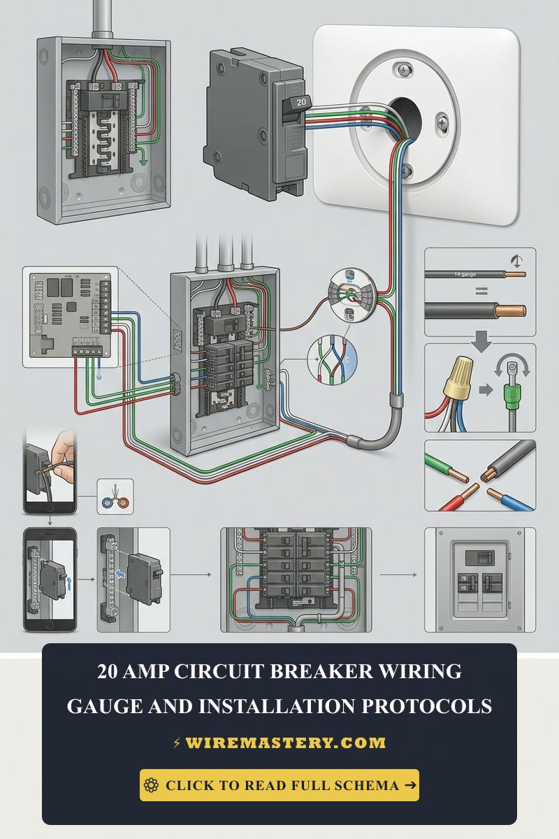
Feed your 12/2 NM-B Romex cable through an approved plastic or metal knockout connector at the top or bottom of the panel box enclosure. Pull the cable line tight and strip away the outer yellow PVC jacket, leaving at least 8 inches of exposed individual conductors inside the panel for clean wire routing management.
🛠️ Panel Wiring Architecture Note: Look closely at the industrial model displayed in your guide graphics. Notice the strict geometrical separation between different conductor lines inside a professional panel layout. The ground lines route directly along the outer metallic framework walls to avoid crowding, the neutrals cluster cleanly into the main silver bus bars, and the black hot wire folds in a precise right-angle accordion curve before snapping securely into the breaker terminal block clamp.
3. Terminating Ground and Neutral Pathways
- Ground Connection: Route the Bare copper wire to the dedicated grounding bus bar strip. Insert it into an open terminal hole and torque the terminal screw firmly.
- Neutral Connection: Route the White wire to the main neutral bus bar block. Secure it under a vacant terminal clamp screw. Note on Modern Panels: If you are deploying an advanced AFCI or GFCI Plug-on Neutral (PoN) breaker, the white wire will terminate directly into the breaker’s built-in terminal rather than routing back to the panel bar framework.
4. Mounting and Hot Wire Termination
Strip exactly 1/2 inch of insulation off your Black hot wire. Insert the raw copper end directly into the terminal lug box clamp of your new single-pole 20-amp breaker and torque the set-screw tightly.
Hook the mounting hook of the breaker chassis onto the plastic alignment rail of the panel box and press the breaker body firmly inward until the metal center jaw snaps solidly onto the live metal bus bar tang.
5. Final Reassembly and Testing Protocols
Carefully replace the deadfront panel cover plate. Punch out the matching metal knockout tab on the deadfront to allow the new breaker toggle to pop through the slot framework. Re-engage the main panel power switch. Toggle your new 20-amp breaker to the “ON” position. Use your digital multimeter to verify a clean 120V AC output across the hot slot and neutral slot terminals of your downstream wall outlets.
NEC Compliance & Official Safety Standards
Adhering to strict electrical installation codes protects your home insurance coverage and prevents catastrophic arc faults. The National Electrical Code strictly regulates branch configurations under NEC Article 210:
- AFCI Safety Protections (NEC 210.12): Modern building codes dictate that nearly all newly installed 120V residential 20-amp branch circuits feeding family living areas, kitchens, and bedrooms must feature Arc-Fault Circuit Interrupter (AFCI) protection to shield against hidden spark hazards behind walls.
- Grounding and Bonding Rules (NEC Article 250): Every downstream receptacle on a 20-amp node must maintain solid grounding continuity to trigger an instant overcurrent trip during an insulation dropout fault.
For current NFPA 70 guidance on 20-amp branch circuits, conductor sizing, and breaker installation, consult the Official NFPA 70: National Electrical Code (NEC).







