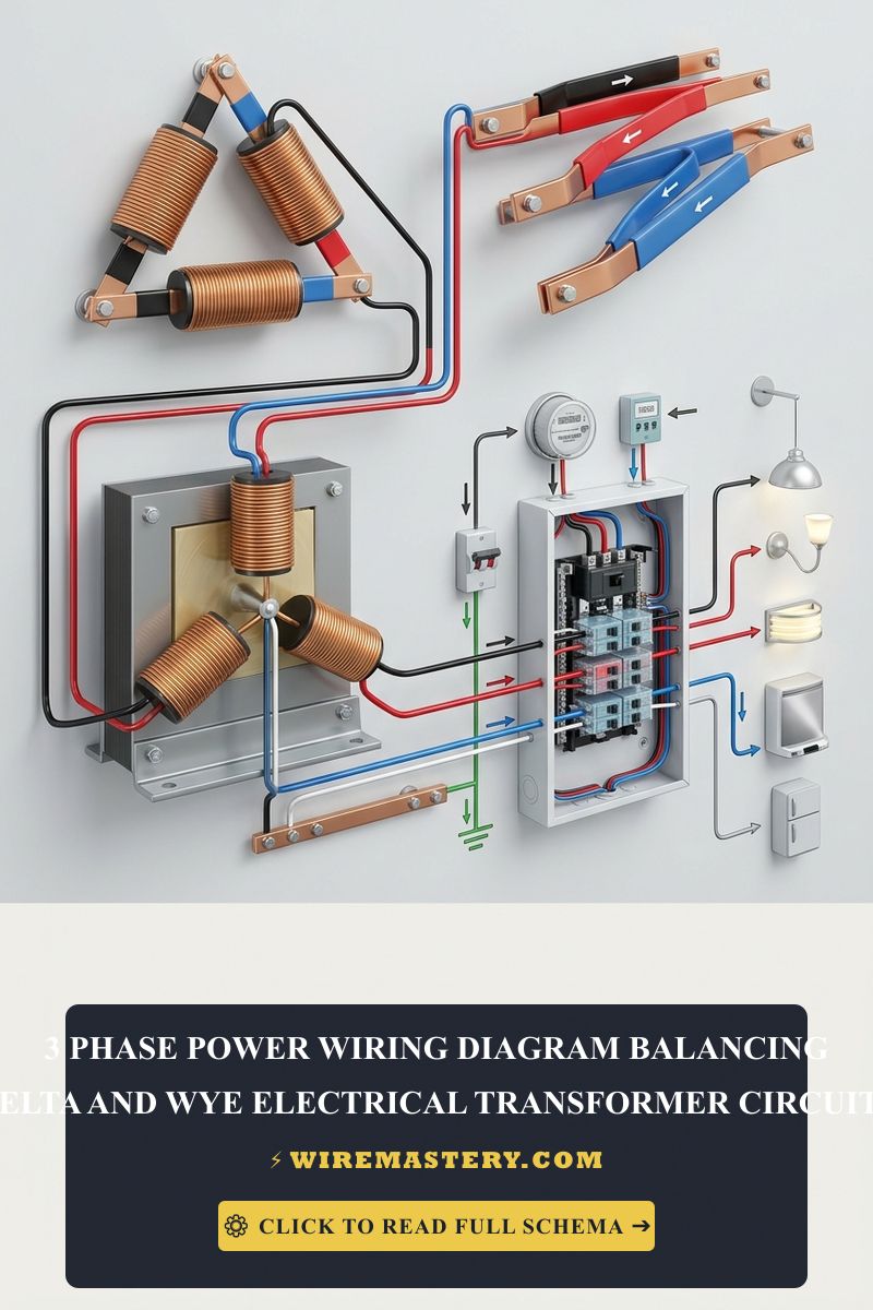
3-Phase Power Wiring Diagram: Balancing Delta & Wye Circuits
Three-phase power systems are integral to modern electrical distribution, particularly in commercial and industrial applications. Understanding the wiring diagrams for delta and wye transformer circuits is critical for ensuring balanced loads, efficient energy delivery, and compliance with safety standards. This guide will delve deeply into the technical aspects of three-phase power wiring, focusing on balancing delta and wye circuits, essential tools, wire gauges, and adherence to NEC codes.
Understanding Three-Phase Power
Three-phase power consists of three alternating currents that are offset in time by one-third of a cycle, allowing for a more constant power flow compared to single-phase systems. The two common configurations for three-phase circuits are delta (Δ) and wye (Y).
Delta Configuration (Δ)
In a delta configuration:
- Each winding of the transformer connects in a triangular shape.
- The line voltage equals the phase voltage.
- It is typically used for higher load applications.
Wye Configuration (Y)
In a wye configuration:
- Each winding connects to a common neutral point, forming a star shape.
- The phase voltage is lower than the line voltage by a factor of √3.
- It is often used for lower load and residential applications.
Balancing Loads in Three-Phase Systems
Balancing loads in a three-phase system is crucial for optimal performance. An unbalanced system can lead to overheating, increased losses, and equipment failure. Here’s how to achieve balance:
Load Calculation
- Determine Total Load (in Watts):
- Calculate the total power consumption of all connected devices.
- Divide by Phase Count:
- Divide total load by three to find the ideal load for each phase.
Balancing Techniques
- Redistribute Loads:
- Move some loads from one phase to another to equalize.
- Use Transformers:
- Deploy transformers to create additional phases or adjust voltage levels.
Wiring Diagrams
Delta Wiring Diagram
A delta wiring diagram shows how the three windings connect in a triangle.
      A
      / \
     /   \
B-----C-
Connections:
- Connect each end of the windings to form a closed loop.
- Each corner represents a phase (A, B, C).
-
Phase Connections:
- Connect the output to the load directly from each phase.
Wye Wiring Diagram
A wye diagram illustrates how the windings connect to a neutral point.
       N
      /|\
     / | \
A B C-
Connections:
- Each winding’s start connects to a common neutral point (N).
- The other ends connect to the phases (A, B, C).
-
Phase Connections:
- The neutral point can provide a return path for unbalanced loads.
Tools and Equipment
To work with three-phase systems, specific tools and equipment are necessary:
Essential Tools
- Multimeter: To measure voltage, current, and resistance.
- Clamp Meter: For non-invasive current measurement.
- Insulation Resistance Tester: To check insulation integrity.
- Wire Strippers/Cutters: For preparing wires.
- Screwdrivers: For terminal connections.
- Torque Wrench: To ensure proper tightening of connections.
Safety Gear
- Insulated Gloves: Protect against electrical shocks.
- Safety Glasses: Prevent eye injuries.
- Hard Hat: For protection against falling objects.
Wire Gauges and Selection
Choosing the Right Wire Gauge
Wire gauge selection is critical for safety and efficiency. The American Wire Gauge (AWG) standard is commonly used.
Considerations for Wire Selection
- Current Rating: Ensure the wire can handle the load.
- Voltage Drop: Choose a gauge that minimizes voltage drop over distance.
- Ambient Temperature: Account for temperature ratings of wires.
Common Wire Gauges for Three-Phase Systems
- 12 AWG: Suitable for circuits up to 20A.
- 10 AWG: For circuits up to 30A.
- 8 AWG: Used for higher loads, up to 40A.
NEC Codes and Compliance
Adhering to the National Electrical Code (NEC) is essential for safety and legal compliance.
Important NEC Regulations
- Article 310: Covers conductors for general wiring.
- Article 440: Addresses motor circuits.
- Article 250: Focuses on grounding and bonding.
Key NEC Compliance Tips
- Use Properly Rated Equipment: Ensure transformers and breakers meet NEC standards.
- Marking and Identification: Clearly label all circuits and panels.
- Regular Inspections: Schedule routine inspections to ensure ongoing compliance.
Safety Checklist
Before starting any electrical work, ensure the following:
- Power is turned off at the main breaker.
- Use insulated tools and wear appropriate safety gear.
- Verify all connections are tight and properly insulated.
- Test circuits before energizing.
Practical Applications of Delta and Wye Configurations
When to Use Delta
Delta connections are ideal in scenarios such as:
- Large motors requiring high starting torque.
- Industrial applications with heavy machinery.
When to Use Wye
Wye connections are preferred for:
- Residential applications where a neutral is necessary.
- Load balancing in systems with lower power needs.
Troubleshooting Common Issues
Symptoms of Unbalanced Loads
- Flickering lights.
- Overheating of wires or equipment.
- Tripped breakers.
Troubleshooting Steps
- Measure Current on Each Phase: Identify the phase with the highest load.
- Inspect Connections: Look for loose or corroded connections.
- Redistribute Loads: Move equipment to balance the load across phases.
Conclusion
Understanding the intricacies of three-phase power wiring, particularly the balance between delta and wye configurations, is essential for electricians, engineers, and contractors. The safety of electrical installations hinges on proper wiring practices, adherence to NEC codes, and ongoing education about electrical standards. By following best practices for load balancing, selecting appropriate wire gauges, and utilizing the right tools, professionals can ensure efficient and safe electrical systems.
NEC Compliance & Official Safety Standards
Following NEC regulations is crucial for maintaining safe electrical practices. These codes are designed to protect people and property from electrical hazards. For the most current information and updates regarding electrical safety enforcement, refer to the Official NFPA 70: National Electrical Code (NEC).







