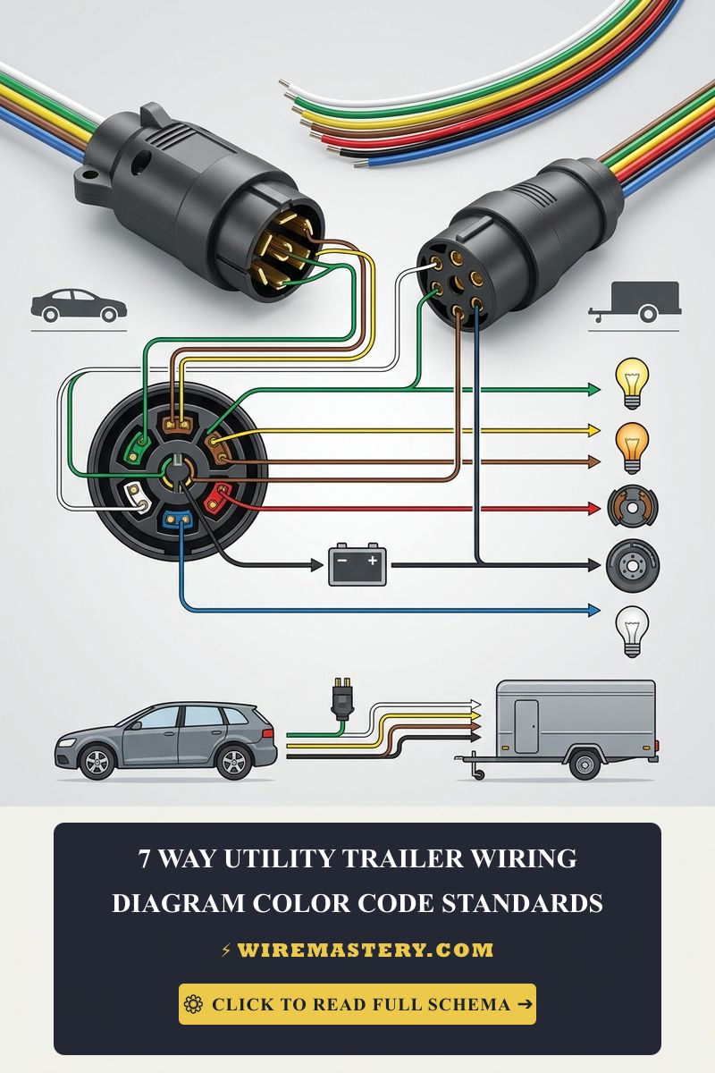
7-Way Utility Trailer Wiring Diagram: Official Color Code Standards
Towing heavy utility trailers, RVs, or equipment haulers safely down United States highways demands an unshakeable low-voltage electrical connection. The auxiliary link between a towing vehicle and a trailer does more than power basic marker lights; it manages high-amperage electronic brake controllers and constant 12V battery charging loops. A single loose blade or a crossed signal wire can lead to catastrophic brake failure or severe legal violations on the road.
The official 7-way utility trailer wiring diagram standards, RV blade pinout configurations under SAE J2863 guidelines, and mechanical troubleshooting steps engineered for North American towing frameworks.
Core Structural Towing Benchmarks
Before slicing your multi-conductor trailer harness, verify your automotive electrical thresholds:
- Official Governing Standards: Unlike residential grids regulated by the NEC, highway trailer circuits fall strictly under the jurisdiction of the Society of Automotive Engineers (SAE) and the Federal Department of Transportation (DOT).
- Connector Profile: The standard North American 7-way connector utilizes flat brass blades encased in a heavy-duty plastic or metal housing, commonly referred to as the standard RV/Trailer blade plug.
- Grounding Priority: The trailer chassis must never be used as a shortcut return path without a dedicated, heavy-gauge solid ground wire running directly through the main 7-way plug framework.
Technical Materials and Trailer Wiring Checklist
Executing a clean, weather-resistant vehicle-to-trailer termination requires specialized automotive tools and electrical supplies:
| Automotive Trade Tool | Primary Technical Purpose |
|---|---|
| Heavy-Duty Terminal Crimper | Compresses insulated ring terminals onto thick 10 AWG to 14 AWG strands without loose play. |
| Dual-Wall Heat Shrink Tubing | Marine-grade adhesive-lined tubing to seal outdoor wire splices against road salt and moisture. |
| Digital Auto-Ranging Multimeter | To map individual vehicle blade pins and confirm real-time 12V DC power output. |
| Dielectric Connector Grease | Silicone-based compound applied to blades to block oxidation, corrosion, and water ingress. |
Official 7-Way Trailer Wire Color Code & Pinout Matrix
To guarantee multi-vendor compatibility between truck manufacturers (Ford, Chevy, RAM, Toyota) and trailer builders, North American configurations follow a strict layout. Below is the official structural blueprint for standard 7-way blade plugs mapped according to standard SAE automotive color conventions:
| Plug Blade Position | Standard Wire Color | Conductor Gauge (AWG) | Primary Automotive Function |
|---|---|---|---|
| Pole 1 (Left-Center) | White | 10 AWG or 12 AWG | Main System Ground: Core return loop to the vehicle frame. |
| Pole 2 (Top-Left) | Blue | 12 AWG or 14 AWG | Electric Brakes: Main power feed from the in-cab brake controller. |
| Pole 3 (Top-Right) | Green | 16 AWG | Tail & Running Lights: Powers side markers and license plate halos. |
| Pole 4 (Right-Center) | Black | 10 AWG | 12V Battery Charge: Continuous auxiliary power to charge RV batteries. |
| Pole 5 (Bottom-Left) | Red | 16 AWG | Left Turn & Stop: Left blinker line and secondary brake filament. |
| Pole 6 (Bottom-Right) | Brown | 16 AWG | Right Turn & Stop: Right blinker line and secondary brake filament. |
| Pole 7 (Center Pin) | Yellow / Purple | 16 AWG | Reverse Lights: Back-up illumination or surge brake lockout solenoids. |
🚨 CRITICAL ROAD SAFETY WARNING: The Traps of “RV vs. Utility” Wiring While the table above outlines the traditional RV standard (the absolute benchmark for modern factory trucks), some legacy utility trailer manufacturers utilize alternative traditional industrial colors where the Green and Brown lines are completely reversed (Green for Left Turn, Yellow for Right Turn). Never wire a plug blindly based on color. Always use a digital multimeter or a 7-way circuit tester on your vehicle’s bumper socket to verify which blade outputs the blinker signal before terminating your trailer plug pins.
Step-by-Step 7-Way Blade Plug Installation Manual
1. Harness Preparation and Outer Jacket Stripping
Expose approximately 2 inches of the main multi-conductor trailer cable sheath using a dedicated cable slicer. Be extremely careful not to slice the inner colored wire insulation jackets. Strip exactly 1/2 inch of insulation from each of the seven individual stranded lines using your wire strippers. Twist the raw copper strands tightly to prevent stray hairs from shorting adjacent terminals.
2. Terminating the Blade Connections
Unscrew the rear strain relief collar of the new 7-way plug housing and slide it over the cable sheath. Insert each color-coded stranded wire into its respective brass terminal slot according to the SAE pinout layout. Tighten the terminal clamping screws firmly.
Ensure the heavy White ground line (10 AWG) and the heavy Black power line (10 AWG) are seated perfectly with maximum screw contact, as these two lines handle the highest current loads across the electrical framework.
3. Weatherproofing and Housing Assembly
Pack the rear terminal block area with high-quality dielectric grease to insulate the connections against rain dropout. Slide the outer protective plastic sleeve forward over the core insert and secure the mechanical locking screw. Tighten the rear strain relief clamp over the outer main cable bundle to prevent the wires from ripping loose during sharp highway turns.
4. Establishing a Solid Chassis Ground Ground
Go to the trailer tongue frame. The white ground wire exiting the harness must be secured directly to clean, bare structural steel. Grind away any rust or protective paint from the metal frame, crimp a heavy-duty copper ring terminal onto the wire line, and anchor it firmly using a self-tapping screw and a star lock washer to prevent road vibrations from loosening the connection.
Troubleshooting Common Towing Electrical Faults
- Trailer Brakes Engage When Turn Signals Flash: This indicates a catastrophic floating ground fault. If the white main ground wire is loose, broken, or corroded, the high-amperage current will attempt to find a return path to the truck through the smaller turn signal filaments. Re-secure the main ground connection to the trailer steel frame immediately.
- Auxiliary Trailer Battery Fails to Charge: Check the truck’s engine bay fuse block. Most vehicle manufacturers (especially GM and Ford) ship their vehicles with the main 12V auxiliary charge line fuse uninstalled or disconnected from factory delivery. You may need to insert a dedicated 30-amp or 40-amp J-Case fuse into the truck box.
- Intermittent Light Blinking While Driving: Inspect the bumper plug socket latch. If the safety clip on the truck door hook is broken, the plug will slide out slightly under heavy highway wind drag, creating intermittent terminal gaps.
Regulatory Compliance & DOT Safety Standards
Adhering to strict automotive standards keeps your vehicle legal and fully insurable during commercial or private towing operations. Federal regulations managed by the Department of Transportation (DOT) and local state highway patrols mandate that all utility trailers traveling on public infrastructure maintain fully functioning independent braking systems, active breakaway safety switches, and continuous illumination halos across rear perimeters. Non-compliance can result in severe legal citations, impoundment, or denial of insurance coverage during an accident.
For current trailer wiring, connector, lighting, and towing requirements, consult the official resources provided by the National Highway Traffic Safety Administration and applicable national towing authorities.
Conclusion
This guide covers wiring a 7-way utility trailer plug guarantees reliable towing operations and ensures full alignment with official highway safety standards. By avoiding color-coding shortcuts, grinding down clean bare-steel grounding pathways, and protecting brass blades with dielectric grease, you build a professional-grade automotive connection. Prioritize safety testing, verify circuit signals using auto-ranging multimeters, and haul your cargo with total code-compliant confidence.