Air Conditioner Connections: Residential HVAC Wiring Standards
Introduction
Integrating a central air conditioning system into a residential electrical grid requires an absolute understanding of two completely independent electrical systems working in tandem. The outdoor condensing unit demands a dedicated high-amperage 240V branch power circuit to drive the compressor and fan motors, while simultaneously interfacing with an isolated low-voltage 24V AC communication loop controlled by the indoor thermostat. Miscalculating wire gauges or crossing line-voltage lines with signal control lines can instantly destroy expensive HVAC electronic circuit boards or trigger catastrophic structural fire hazards.
The exact dual-phase wire selections for central air conditioners, thermostat signal mapping conventions, and strict electrical safety standards enforced under NEC Article 440.
Core HVAC Electrical Sizing Parameters
Before pulling structural cables to your outdoor condenser unit pad area, verify these official equipment rating plate metrics:
- Minimum Circuit Ampacity (MCA): Stamped directly on the manufacturer nameplate. This specific metric dictates the minimum thickness (AWG) of the branch conductors required to handle the unit load safely.
- Maximum Overcurrent Protective Device (MOPD): Specifies the absolute maximum fuse or circuit breaker size allowed to safeguard the unit. Utilizing a larger overcurrent device violates federal building codes.
- Line Voltage vs. Control Voltage: Outdoor AC condensers are high-voltage 240V single-phase, dual-hot systems (using no neutral line), which operate completely independent of the indoor 24V climate signals.
Technical Materials and HVAC Installation Checklist
Executing a clean, code-compliant air conditioner termination loop requires specialized trade tools and heavy-duty weatherproof electrical components:
| HVAC Installation Tool / Supply | Primary Technical Purpose |
|---|---|
| Liquid-Tight Flexible Conduit (Whiplash) | Weatherproof flexible outer conduit casing required to shield 240V conductors from moisture and lawnmowers. |
| Non-Contact AC Voltage Tester | Crucial tool to verify 100% circuit de-energization inside the external disconnect box before trade work. |
| Heavy-Duty Torque Driver | For torqueing terminal block lug screws inside the compressor compartment to exact inch-pound thresholds. |
| Digital Auto-Ranging Multimeter | Measures exact supply voltages across L1 and L2 lines and diagnoses low-voltage 24V control loops. |
High-Voltage 240V Power Supply Wiring Matrix
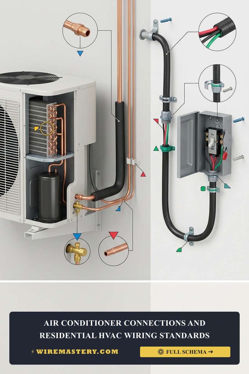
The main branch circuit feeding the outdoor AC compressor runs from your distribution panel directly to an outdoor weatherproof HVAC disconnect box mounted on the building exterior wall cavity near the condenser pad.
According to NEC Article 440, you must run a three-conductor line containing two individual hot lines and one safety equipment ground (No Neutral).
Standard Condenser Ampacity Sizing Benchmarks (Copper Wire)
| AC Unit Tonnage Rating | Typical Nameplate MCA | Required Conductor Gauge (AWG) | MOPD Fuse / Breaker Rating |
|---|---|---|---|
| 1.5 to 2 Tons | 15 - 20 Amps | #12 AWG Copper (Yellow Romex / THHN) | 20 Amp Double-Pole |
| 2.5 to 3 Tons | 21 - 30 Amps | #10 AWG Copper (Orange Romex / THHN) | 30 Amp Double-Pole |
| 3.5 to 5 Tons | 31 - 45 Amps | #8 AWG Copper (Black THHN in Conduit) | 40 or 50 Amp Double-Pole |
Step-by-Step Air Conditioner Connection Walkthrough
1. Circuit Isolation and Multi-Tester Verification
Locate your property’s main electrical panel block. Disengage the dedicated double-pole circuit breaker feeding the outdoor climate loops. Navigate to the outdoor disconnect box near the condenser, open the safety door lid, and pull out the mechanical disconnect block plug. Use your digital multimeter across the incoming terminal lugs to confirm the branch reads a complete 0V AC state before removing any hardware safety shrouds.
2. Terminating the 240V Line Voltage (L1 and L2 Connections)
Route your high-voltage copper conductors (typically THHN wires wrapped in a weatherproof liquid-tight flexible whip casing) into the condenser interior terminal block housing compartment:
- Connect the Incoming Hot Phase 1 (Black wire) to the lug terminal labeled L1 or T1.
- Connect the Incoming Hot Phase 2 (Red or secondary Black line) to the lug terminal labeled L2 or T2.
- Connect the Equipment Ground line (Bare copper or Solid Green) to the hex-shaped green grounding lug bonded directly to the unit’s metal chassis casing frame.
🚨 CRITICAL CONTRACTOR WARNING: Never Connect a Neutral Wire to a Condenser Amateur installers frequently mistake 240V HVAC loops for standard 120V household outlets and attempt to hook up a white wire to the terminal block. Central AC compressors operate strictly on a balanced dual-hot phase potential (120V + 120V = 240V). There is no terminal for a neutral wire inside an outdoor condensing unit block. Introducing a current-carrying neutral wire into a line-voltage component will cause severe system damage, ruin your compressor windings, and trigger immediate dead-short fire hazards.
3. Mapping the Low-Voltage 24V Thermostat Control Signals
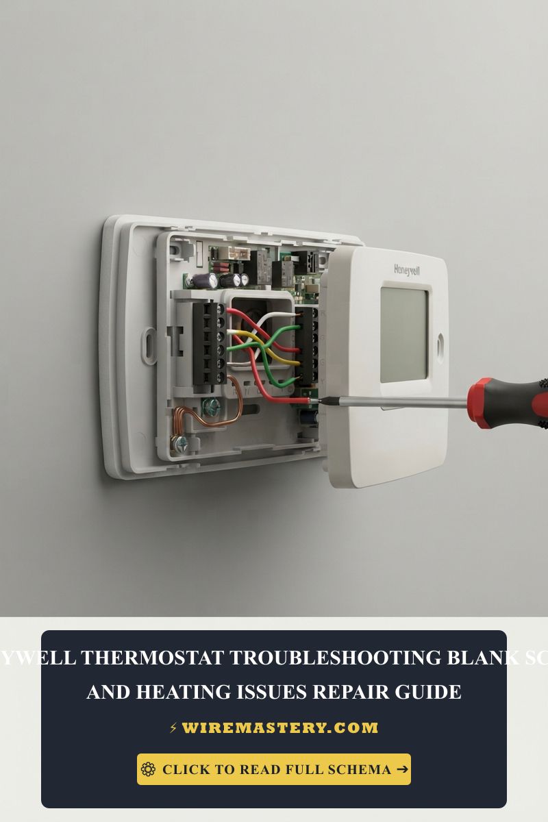
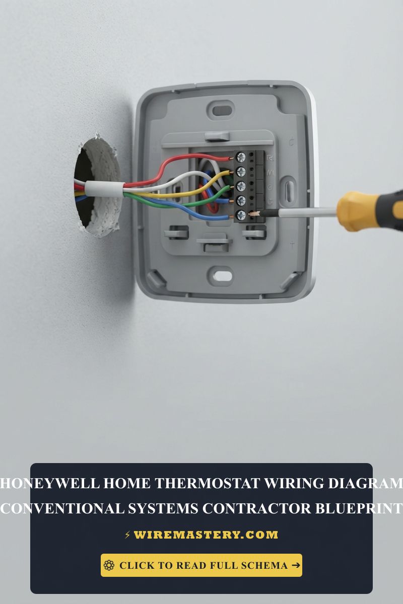
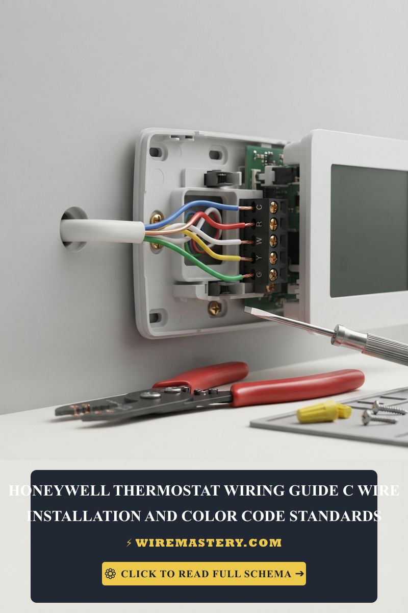
Once the heavy power lines are torqued down to specification limits, locate the small, low-voltage control terminal strip situated on the side panel framework. Pull your 18 AWG solid copper thermostat wire lines into the enclosure box and splice them to the unit control leads using waterproof wire connectors:
- The Y Terminal (Typically Yellow wire): This line transmits the 24V AC call signal from the indoor thermostat when cooling is requested, energizing the high-voltage magnetic contactor coil to pull in and turn on the compressor.
- The C Terminal (Typically Blue or Black wire): The common return line that completes the 24V AC power loop back to the indoor furnace or air handler control transformer.
Troubleshooting Common HVAC Connection Faults
- The Contactor Clicks but the Compressor Fails to Start: This behavior indicates a faulty dual-run capacitor or loose line-voltage lug connections on L1 or L2. Turn off the breaker and check terminal tightness using an insulated torque driver.
- Thermostat Reboots Whenever Cooling Cycles Engage: This occurs when the low-voltage control transformer is overloaded or short-circuited. Verify that no bare copper strands on the 18 AWG Y and C terminal nodes are touching each other or brushing against the metallic casing walls.
- Outdoor Fan Motor Runs but the Air Blows Warm Inside: Check the outdoor disconnect box fuses. In a 240V system, if one fuse blows while the other remains intact, the fan motor might still turn on at 120V, but the high-amperage compressor will remain starved of dual-phase power and stay completely offline.
NEC Compliance & Official Safety Standards
Adhering to strict construction codes shields your home investment, maintains property valuation, and ensures full insurance compliance. The National Electrical Code strictly regulates heavy-duty residential cooling gear under NEC Article 440 - Air-Conditioning and Refrigerating Equipment. Key compliance measures dictate that an external safety disconnect switch must be located within a direct, unobstructed sightline from the condensing unit (no more than 50 feet away) to allow a field service technician to safely cut all power in an emergency.
For the NFPA 70 provisions relevant to this guide on Air Conditioner Connections: Residential HVAC Wiring Standards, consult the Official NFPA 70: National Electrical Code (NEC).