Air Conditioning Diagrams: Residential AC System Wiring Guide
Deciphering residential air conditioning diagrams is essential for safe HVAC work. A central ac split system uses 240V for heavy motors and 24V for control logic. Proper configuration of an air cond unit prevents short-circuits and protects control boards.
This guide breaks down the standard residential AC system wiring schematics, terminal block configurations, and safety parameters enforced under NEC Article 440.
Core Schematic Sizing Benchmarks
Before tracking conductor paths through an HVAC system schematic, establish your circuit baselines:
- Dual-Voltage Separation: Schematics always separate high-voltage line current (represented by thick solid lines) from low-voltage control loops (represented by thin or dashed lines).
- Contactor Logic: The outdoor contactor acts as a heavy-duty magnetic relay switch. When the 24V coil receives current, it pulls in the mechanical contact bars to close the high-voltage 240V path feeding the compressor.
- Overload Protections: Modern central air schematics feature an internal thermal overload switch wired in series with the compressor motor windings to trip the system if temperatures spike dangerously.
Technical Materials and Testing Equipment Checklist
Safely auditing and tracing structural AC wiring layouts requires specific field instruments and safety gear:
| HVAC Diagnostic Tool | Primary Technical Purpose |
|---|---|
| Auto-Ranging Multimeter | Essential tool to verify clean 240V AC line power and trace 24V AC pilot signal continuity. |
| Non-Contact Voltage Detector | Audibly confirms complete power isolation inside the external disconnect box before touching lugs. |
| Wire Nut Connectors (Waterproof) | Silicone-filled outdoor caps required to seal 24V signal control splices against weather dropouts. |
| Insulated Needle-Nose Pliers | For seating tight low-voltage thermostat wire leads onto the crowded system terminal strip. |
Decoding the Central AC System Terminal Board: Wiring Diagram Aircon Guide
To accurately interpret an advanced air conditioner connection diagram or configure a comprehensive wiring diagram aircon matrix, a technician must look past generic field labels. Within any complex residential central air conditioning system, mapping out individual solid-conductor pairs requires a disciplined terminal audit before closing the subpanel breaker box enclosure.
Low-Voltage Control Terminal Mapping (24V AC)
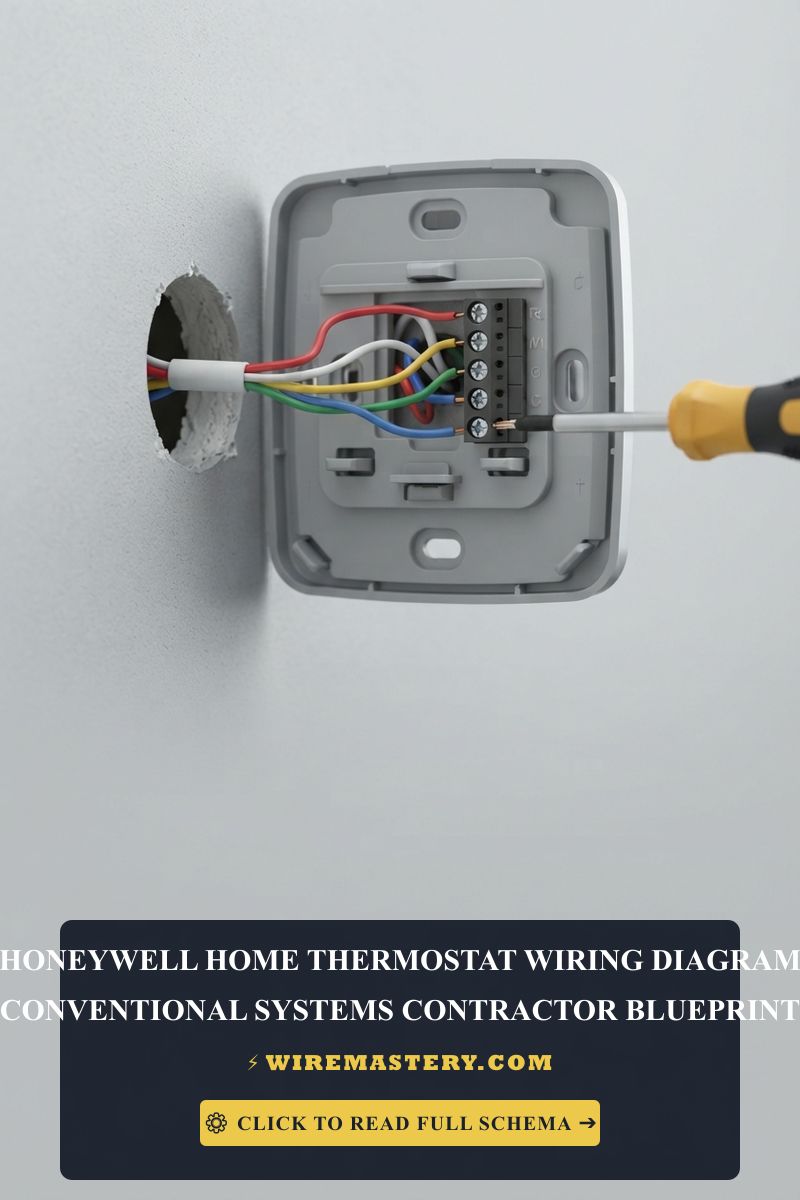
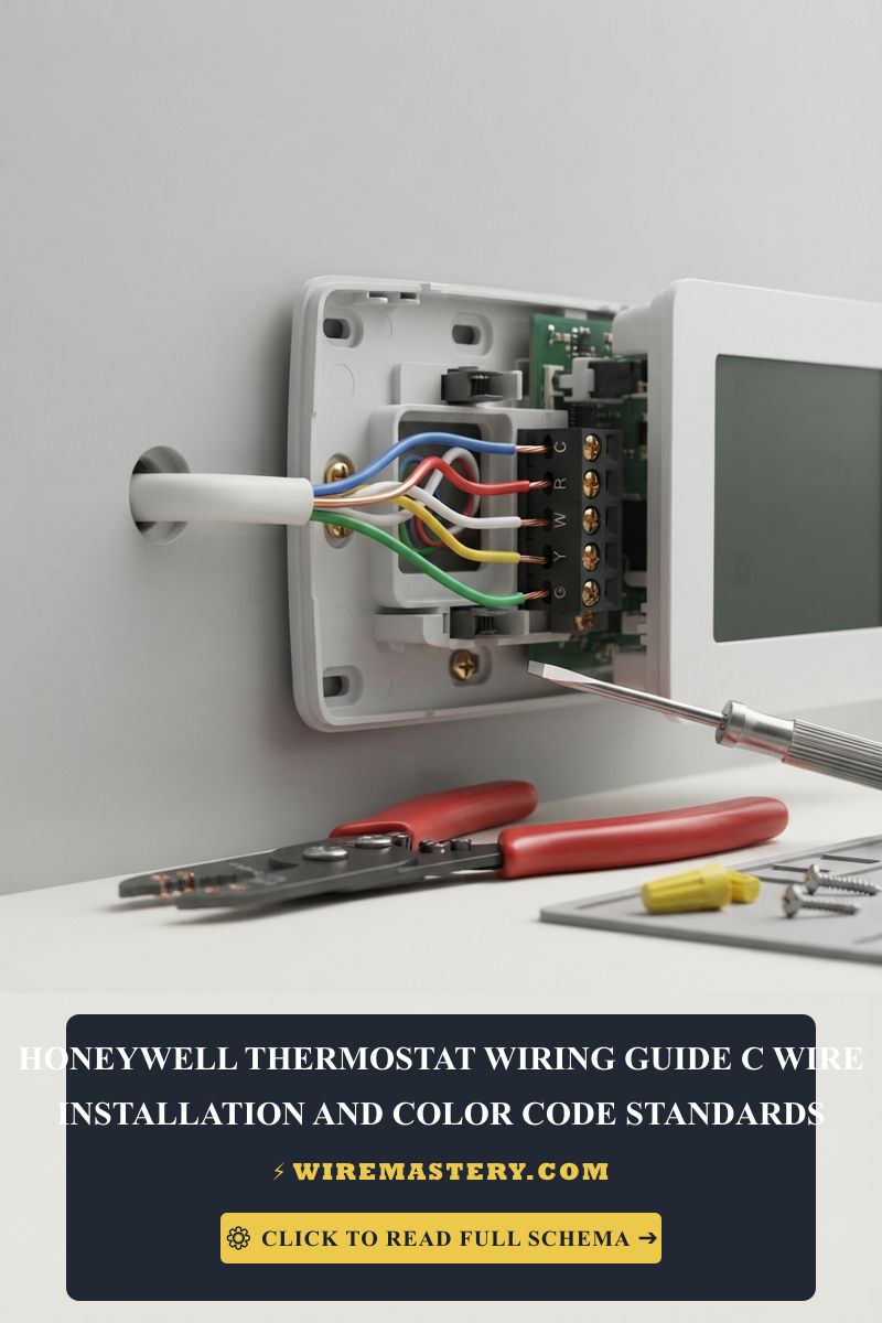
| Terminal Letter | Standard Wire Color | Schematic Target & Function |
|---|---|---|
| R | Red | 24V AC Power: Continuous hot feed coming straight from the indoor transformer. |
| Y / Y1 | Yellow | Cooling Stage 1: Sends a 24V signal to pull in the outdoor compressor contactor coil. |
| G | Green | Indoor Fan Relay: Energizes the indoor blower motor to circulate air through ducts. |
| C | Blue / Black | Common Return: Completes the 24V loop back to the grounded transformer side. |
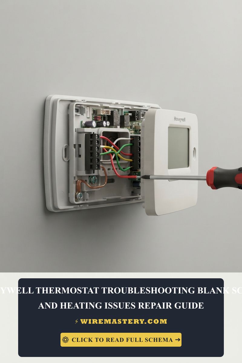
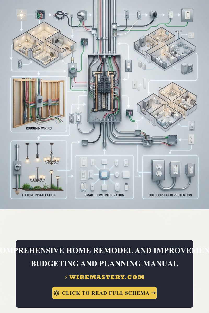
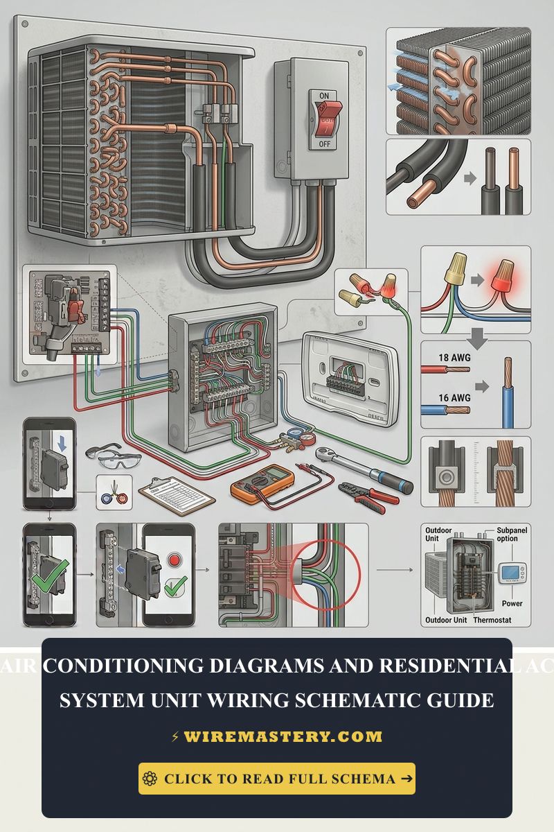
🛠️ Contractor Blueprint Reality Check: Look closely at the professional wiring layout displayed in your guide banner assets. Notice how the thick stranded lines supply 240V power to the contactor terminals while the thin 18 AWG copper wires map cleanly to the control ports. When tracking an unlabelled field bundle, never guess conductor pathways based on insulation colors alone. Always trace the line back to its labeled terminal block anchor point to avoid blowing the system’s 3-amp blade fuse.
High-Voltage 240V Condenser Power Schematics
The high-voltage side of a central air conditioner schematic ignores the white neutral line entirely. To power the heavy compressor pump and outdoor fan, the circuit requires a two-phase dual-hot layout (Line 1 and Line 2) originating from a double-pole breaker block:
-
- Leaving out the C-Wire Connection: Modern smart thermostats require a dedicated C (Common) link to avoid parasitic power stealing, contactor chattering, and compressor short-cycling.
- Line 2 (L2 - Red or Black): Connects to the secondary line terminal of the disconnect box and passes to Terminal 2 of the contactor.
- T1 and T2 (Load Side): Output terminals that send the 240V current directly to the run capacitor and the compressor motor windings once the contactor coil is pulled in by the thermostat.
- Equipment Ground (Green / Bare Copper): Bonds the exterior metal shell housing to the main service panel ground strip to eliminate chassis electrification risks.
Common Blueprint and Connection Faults to Avoid
- Leaving out the C-Wire Connection: Standard legacy thermostats ran on dry batteries, but modern smart climate systems demand a dedicated C (Common) link on the schematic. Bypassing the C-wire forces smart chips to steal power from the Y cooling loop, which triggers contactor chattering and short-cycles the compressor motor.
- Crossing Low-Voltage and High-Voltage Terminals: Attempting to splice a 24V thermostat wire directly onto a 240V contactor line creates an instantaneous explosion that melts the thermostat faceplate and destroys the indoor HVAC circuit board components.
- Neglecting Run Capacitor Discharge Rules: Dual-run capacitors store massive amounts of high-voltage electrical energy even after the main circuit breaker is switched off. Always discharge the capacitor terminals using an insulated screwdriver before handling the surrounding compressor leads to avoid severe shock shocks.
NEC Compliance & Official Safety Standards
Adhering to strict national structural codes keeps your property safe, insurable, and code-compliant. The National Electrical Code strictly regulates industrial refrigeration and residential cooling systems under NEC Article 440. Key schematic enforcement rules dictate that an external safety disconnect switch box must be installed within a direct, unobstructed sightline from the air conditioning unit (no more than 50 feet away) to guarantee a service technician can completely de-energize the network in an emergency.
For current NFPA 70 guidance on air-conditioning disconnects, branch-circuit conductors, grounding, and HVAC equipment wiring, consult the Official NFPA 70: National Electrical Code (NEC).
Conclusion
This article explains air conditioning diagrams and execution rules builds a robust foundation for flawless residential HVAC automation upgrades. By tracking your high-voltage 240V L1/L2 paths, matching 24V signal leads to their correct terminal block letters, and respecting mandatory NEC disconnect clearance lines, you build a professional-grade home environment. Prioritize double-pole breaker power testing, utilize certified auto-ranging multimeters, and wire every phase with code-compliant care.