Connection Light Switch Diagrams: 4-Way Switching Topologies
Introduction
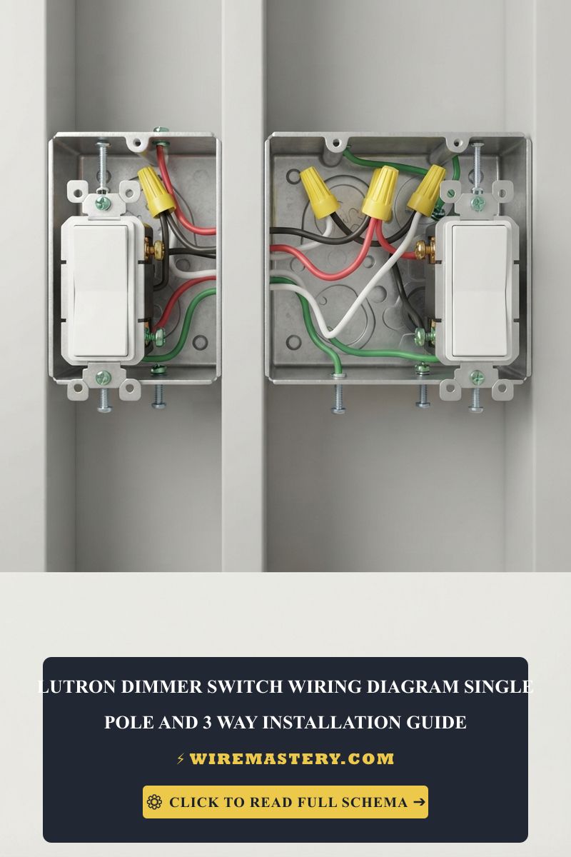
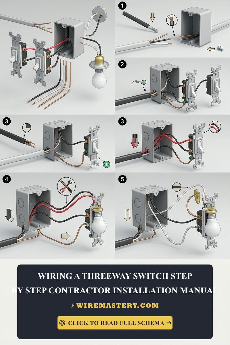
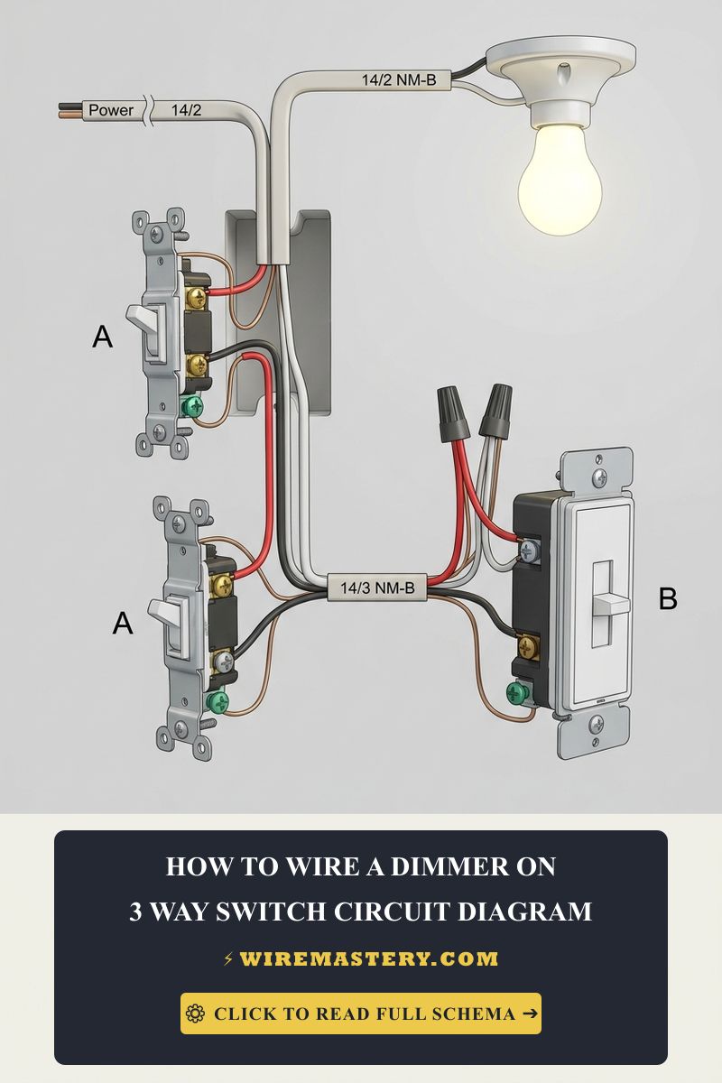
Analyzing and executing a code-compliant residential installation based on an advanced connection light switch diagram network demands a disciplined operational mastery of multi-point terminal matrix switching, traveler routing paths, and magnetic loop circuit geometry. In general residential wiring layouts, managing a lighting load from one or two separate wall boundaries is functionally straightforward, utilizing single-pole or standard 3-way toggle switches. However, spatial architectural scales—such as extended multi-landing stairwells, open-concept great rooms, and long hallway tracks—frequently require deploying a specialized 4-Way Switch Network Topology. Acting as an intermediate logical crossover gate positioned symmetrically between two terminal 3-way units, a 4-way mechanical switch routes alternating current loops across dual parallel input and output traveler screw pairs, demanding absolute precision during high-density box wire packing.
This systems reference manual outlines the electrical engineering layout of multi-point switching networks, terminal pin identification rules, and advanced laboratory safety auditing toolkits.
Core Multi-Point Switching Parameters
Before cutting continuous 14/3 NM-B Romex wire coils or landing traveler leads onto device side screws, decode these foundational parameters:
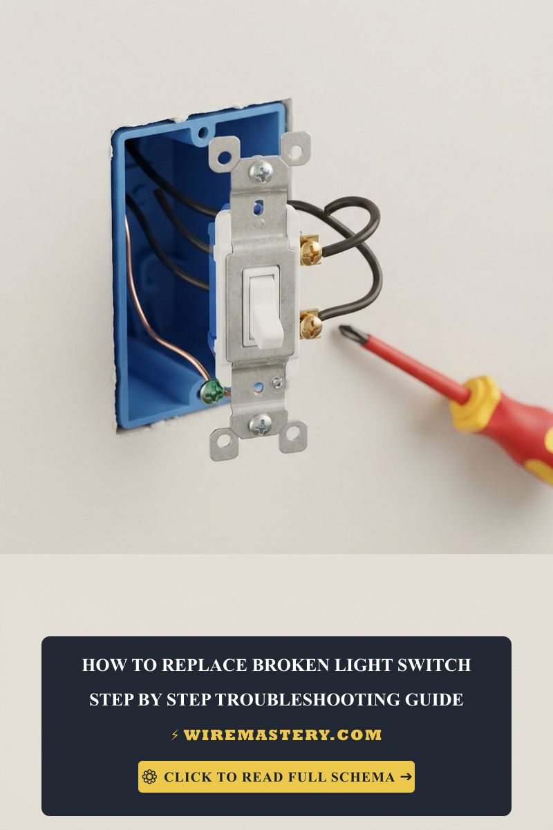
- The Intermediate Crossover Matrix: A 4-way light switch does not possess a dark “Common” terminal lug and cannot serve as an isolated standalone control point. It features strictly four lighter brass-colored terminal screws arranged as two input ports and two output ports. Internally, flipping the mechanical toggle lever alternates the circuit paths between straight-through routing and diagnostic diagonal crossover indexing, altering traveler continuity instantly.
- Conductor and cable selection: The number and arrangement of conductors depend on the existing circuit and installation method. Do not select cable, reuse conductors, or infer their function from color using a generic diagram; a qualified electrician must verify the circuit and applicable requirements.
- Additional control locations: A conventional multi-location circuit uses 3-way controls at the ends and one or more 4-way controls between them. The permitted devices and practical limits depend on the equipment and circuit; there is no universal “infinite locations” rating.
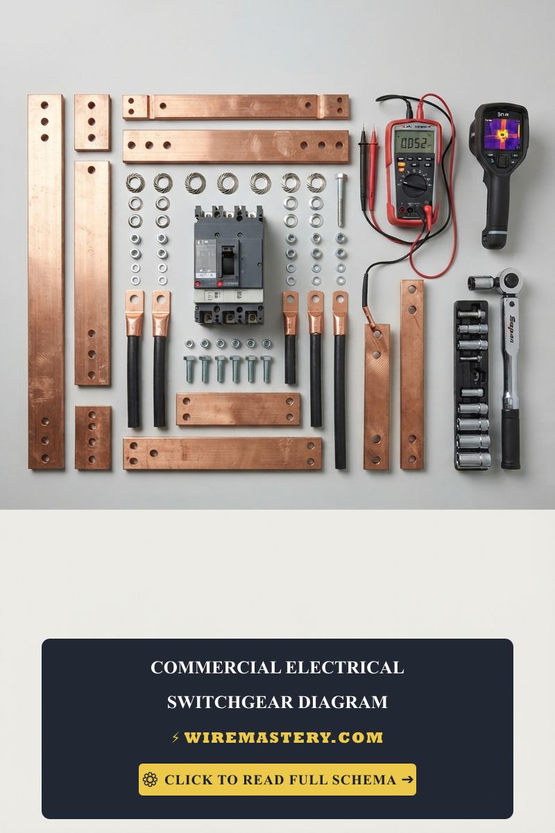
Technical Materials & High-Density Gutter Commissioning Toolkit
Safely sorting multi-point traveler pathways and verifying zero-resistance terminal hooks requires specific certified testing instrumentation and insulated tools:
| Electrical Schematic Tool | Primary Engineering Purpose & Safety Threshold |
|---|---|
| Digital multimeter | Used by a qualified electrician for appropriate circuit diagnostics with an instrument rated for the task. |
| Non-contact voltage detector | Preliminary screening for possible AC voltage; it cannot prove that a conductor is safe to touch. |
| Insulated Linesman Pliers | Hardened jaws to execute code-compliant, tight mechanical pigtail wire twists. |
| Calibrated Dial Torque Screwdriver | Secures side terminal screws to precise manufacturer inch-pound specs to eliminate arcing. |
| Dielectric Electrical Wrap Tape | Heavy-duty PVC tape rated for 600V continuous to fully encapsulate lateral screws. |
Conductor Profiles & Branch Overcurrent Headroom (NEC Table 310.16)
Conductor ampacity depends on more than the nominal breaker rating, including conductor material, insulation, installation conditions, and applicable code requirements. The examples below are common residential copper pairings, not a complete sizing method or instructions for selecting wire for an existing circuit. Have a qualified electrician verify the conductor and overcurrent protection.
- 14 AWG copper: Commonly used on 15-amp residential branch circuits when permitted by the applicable rules and installation conditions. A white cable jacket is a convention, not proof of conductor function.
- 12 AWG copper: Commonly used on 20-amp residential branch circuits when permitted by the applicable rules and installation conditions. A yellow cable jacket is a convention, not proof of conductor function.
Technical Phase 2: 4-Way Switching Layout & Troubleshooting
A common 3-location arrangement has a 3-way control at each end and a 4-way control between them. The 4-way device switches the traveler paths; the actual conductor layout, terminal markings, and cable routing must be confirmed from the equipment instructions and the existing installation. This overview is not a wiring procedure.
1. Planning a 3-Location 4-Way Lighting Layout
Before a project, record the number of control locations, the switch and light models, and any available installation documentation without removing wall plates or exposing wiring. A licensed electrician can identify the circuit layout, select compatible devices and conductors, calculate box fill, and complete the installation under local requirements. Do not energize an open switch box or use a non-contact tester alone to establish that conductors are de-energized.
Conductor identification: Insulation colors alone do not establish a conductor’s function. Some wiring methods allow a conductor with white insulation to be reidentified when used for another permitted purpose, subject to specific code rules. Do not repurpose or mark a conductor based on this overview; have an electrician verify the wiring and local requirements.
Troubleshooting Common Multi-Point Switching Failures
- The light works only in certain switch positions: Several causes are possible, including an incompatible device or wiring that does not match the product diagram. The symptom alone does not identify crossed travelers. Do not remove the switch or test conductors; have an electrician diagnose it.
- The breaker trips when a switch is operated: Stop using the circuit and contact a qualified electrician. Do not repeatedly reset the breaker, pull the switch out, or cover the device with tape.
- The lights flicker or buzz after a dimmer is installed: Check the exact lamp and dimmer compatibility information. If the problem continues, stop using the control and have an electrician inspect the installation; do not retighten or splice conductors yourself.
National Electrical Code Switch Infrastructure Regulations
Adhering to strict national installation codes protects your home electronics investment, maintains property valuation, and ensures full property insurance compliance. The National Electrical Code strictly regulates residential switches, box depths, and grounding continuity under NEC Article 404 (Switches) and Article 314:
- Grounding and device installation: Grounding and switch installation requirements depend on the device, wiring method, and locally adopted code. Follow the listed product instructions and have a qualified electrician verify the installation.
- Box fill: There is no universal 22-cubic-inch box requirement for every 4-way installation. Box fill is calculated from the actual box, conductors, devices, clamps, and applicable code rules; an electrician should verify the correct capacity.
For the NFPA 70 provisions relevant to this guide on Connection Light Switch Diagrams: 4-Way Switching Topologies, consult the Official NFPA 70: National Electrical Code (NEC).
Conclusion
This overview explains how 4-way switches extend lighting control between two 3-way controls. Actual conductor routing, device compatibility, box fill, grounding, and overcurrent protection depend on the installation and local requirements. Use the diagram for the exact listed devices and have a licensed electrician perform or verify the wiring.