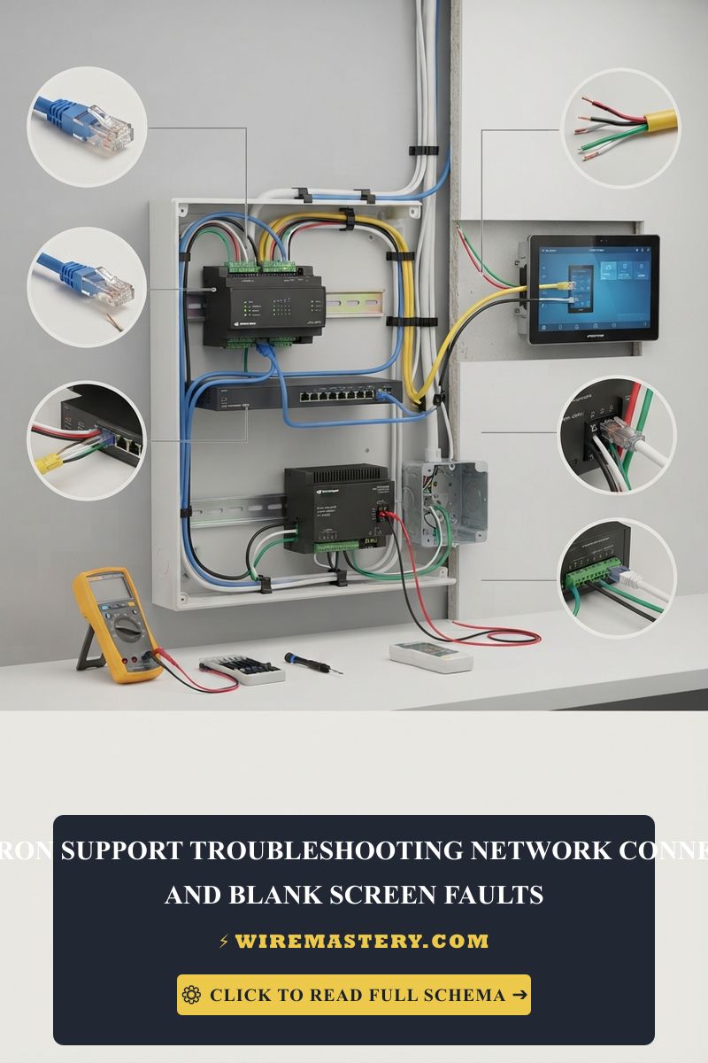
Crestron Support: Troubleshooting Network & Blank Screen Faults
Executing diagnostics inside an enterprise-grade Crestron automation grid demands a highly disciplined approach that combines hardware isolation testing, text console syntax analysis, and low-voltage field measurements. When a high-end command interface or multi-room matrix control system goes completely unresponsive, it halts productivity across corporate boardroom nodes and causes severe luxury residential operational failures. Providing expert, tier-three technical support requires looking past generic reboots; system lockups are almost always clear engineering indicators of high-resistance bus drops, corrupted sector tables inside the Linux sandbox, or inductive noise contamination loops.
This support manual outlines structured diagnostic protocols to resolve network connectivity offline dropouts, recover completely blank touch panel screens, and execute console override scripts safely.
Core Automation Troubleshooting Benchmarks
Before opening expensive equipment racks or modifying terminal connection paths, memorize these structural parameters:
- The 24V AC/DC Separation Rule: Crestron processing hardware isolates low-power logic loops from primary power conduits. Applying unauthorized line voltage to a 4-pin Phoenix block or mismanaging grounding terminals will instantly puncture semiconductor boundaries, melting your smart chip architecture.
- The IPID Handshake Factor: Network connectivity does not rely on raw IP addressing alone. Accessories communicate with the central control processor via a proprietary IPID Hexadecimal identifier, which must match the compiled logic layout file precisely to establish data links.
- Thermal Emergency Lockouts: High-density control processors generate considerable localized thermal heat under full network routing cycles. Enclosing hardware inside non-ventilated equipment racks triggers automated thermal protection lockouts that throw ports offline to preserve silicon integrity.
Technical Materials & Automation Diagnostic Toolkit Checklist
Safely auditing and measuring automated communication buses and resolving network faults requires specific electronics laboratory testing instruments and precise field hand tools:
| Automation Support Tool | Primary Engineering Purpose & Application |
|---|---|
| Digital Auto-Ranging Multimeter | Measures exact DC voltage parameters (0V to 30V) across Phoenix pins to trace power sags. |
| Advanced Fluke Network Analyzer | Maps Category cable data runs, verifying packet handshakes and active PoE voltage outputs. |
| Miniature Phoenix Clamping Driver | Insulated flathead jewelers screwdriver to tighten tiny wire terminal blocks without stripping. |
| USB-to-Serial DB9 Converter Cable | Establishes a direct, hardwired hardware console link to the processor during network lockouts. |
| Anti-Static ESD Grounding Strap | Protects internal motherboard components from body static discharge during hardware extractions. |
Sizing Conductor Gauges & Amperage Boundaries for Cresnet Support
To ensure uncompromised data integrity and prevent high-resistance power drops across extensive structural distances between the central processor and remote hardware access points, you must audit your cabling dimensions according to NEC Class 2 power limitations:
- 18 AWG / 22 AWG Dual-Core Stranded Cable (The Cresnet Standard): True Cresnet lines utilize a specialized four-conductor shielded composite layout. The heavy 18 AWG pair delivers raw 24V DC operating current, while the shielded 22 AWG twisted-pair manages high-frequency digital differential data.
- Distance-Induced Power Sags: Running thin, non-standard conductors over long lengths chokes current loops. If an installer attempts to route a touchscreen over 250 feet using thin 24 AWG wire lines, the voltage drop will starve the panel, causing progressive touchscreen flickering or complete hardware blackouts under continuous graphics processing loads.
The Diagnostics Phase: Tracing the 3 Culprits Behind “Blank Screen” Failures
When a luxury Crestron display interface drops completely dead or exhibits a unresponsive black faceplate, rushed installers frequently replace expensive screens unnecessarily. Before discarding hardware, apply this structured trade diagnostic sequence to isolate the low-voltage fault:
1. The PoE Switch Power Budget Collapse
Modern Crestron panels are powered almost exclusively via Power over Ethernet (PoE).
- The Failure Mode: When an enterprise network switch reaches its maximum cumulative wattage thresholds (due to adding multiple IP cameras or VoIP devices), it cannot feed all ports simultaneously. The switch will automatically isolate and drop ports aggressively, cutting the 48V DC current loop and leaving your Crestron interface completely dark.
- The Support Action: Connect an advanced network tester to the line. Audit the switch’s administrative dashboard to verify that total power draw stays below 80% of its rated headroom limits. If overloaded, integrate a dedicated high-capacity PoE+ midspan injector block to stabilize the line.
2. Crossed Data Lines on Legacy 4-Pin Buses
If your system utilizes older Cresnet-driven displays connected via 4-pin Phoenix blocks, a physical connection error during field terminations can cause immediate system-wide blackouts.
- The Failure Mode: If an installer accidentally swaps the White (Data +) and Blue (Data -) lines, or touches a hot 24V Red wire to the Data pins, the differential signaling potential collapses completely. This throws that specific panel offline and induces heavy noise dropouts across the remaining network tracks.
- The Support Action: Isolate the target block. Use your digital multimeter across the Y and Z pins; the voltage should float rapidly between 1.5V and 3.5V DC, indicating active digital pulse transmissions. If it registers a flat 0V or a continuous +24V, a terminal short or crossed line is actively blocking the link.
3. The Linux File System Sandbox Crash
Crestron 3-Series and 4-Series control processors operate on a highly secure, deterministic embedded Linux software sandbox kernel loop.
- The Failure Mode: Sudden utility grid power outages, continuous brownout sags, or ungraceful hard power cuts during data logging cycles can corrupt internal sector tables or flash memory allocations. The operating system encounters a kernel panic, freezing all communication interfaces and leaving the screen completely blank while internal cooling fans continue to run.
- The Support Action: You must bypass standard network channels and establish a hardwired text console recovery bridge using your USB-to-serial converter cable attached directly to the physical computer port.
Advanced Recovery: Operating the Crestron Text Console
When standard network interfaces collapse, a tier-three automation engineer uses the Crestron Text Console via Toolbox software to run low-level diagnostics. This interface provides an absolute window into the hardware’s core processor layer.
Core Console Diagnostic Command Lines
To clear internal memory caches and analyze system health, establish a secure USB or serial terminal link and execute this strict command sequence:
showhw(Hardware Identification Audit): Type this command and press enter to read the processor’s internal layout parameters. It lists manufacturing board revisions, MAC addresses, and thermal sensor metrics to diagnose overheating.errorestatus(System Error Log Analysis): This script prints out the internal error log history. It identifies active buffer overflows, dead-loop scripts, or missing compiled logic symbols that are freezing your automation framework.iptable -w(IP Table Verification): Displays the active runtime IP Table grid. Use this to confirm that the touch panel’s matching Hexadecimal ID (IPID) is successfully linked to the central control processor.restore(Emergency Factory Overhaul): The final recovery option for fully corrupted file systems. Running this script wipes out all corrupted memory allocation tables and returns the hardware flash sectors to absolute clean factory defaults.
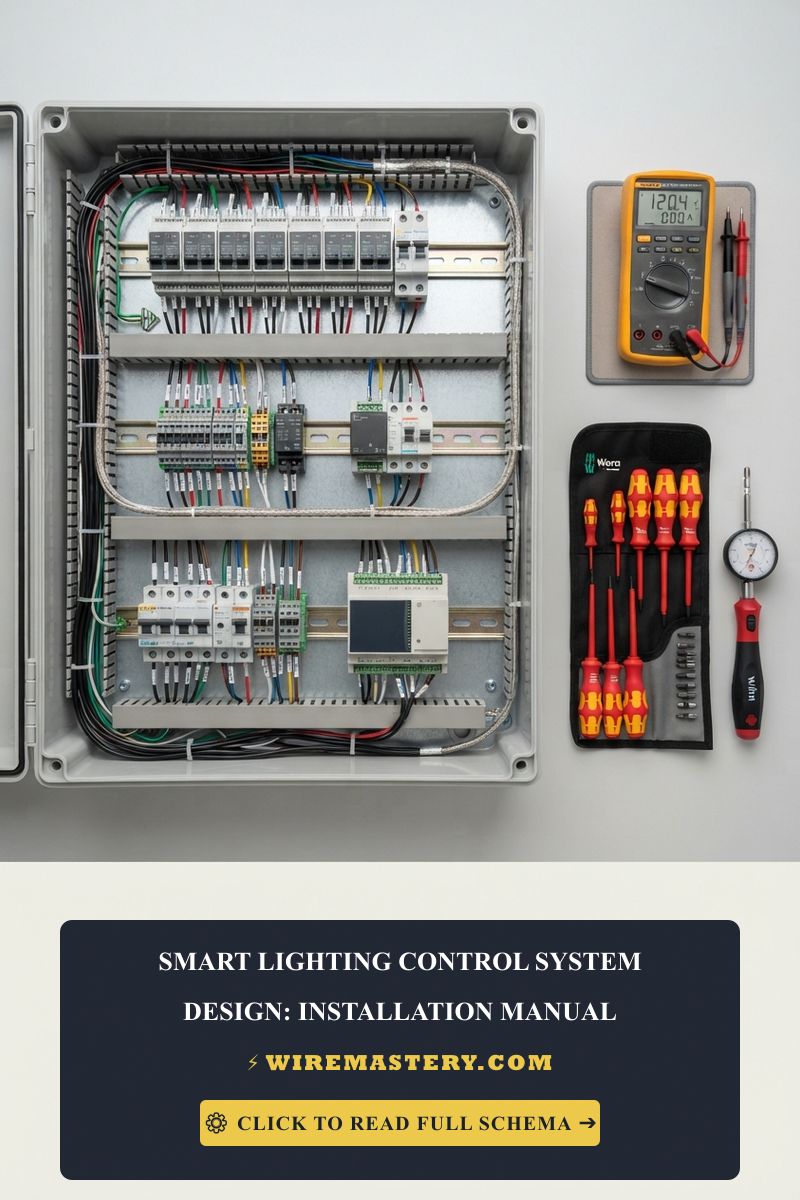
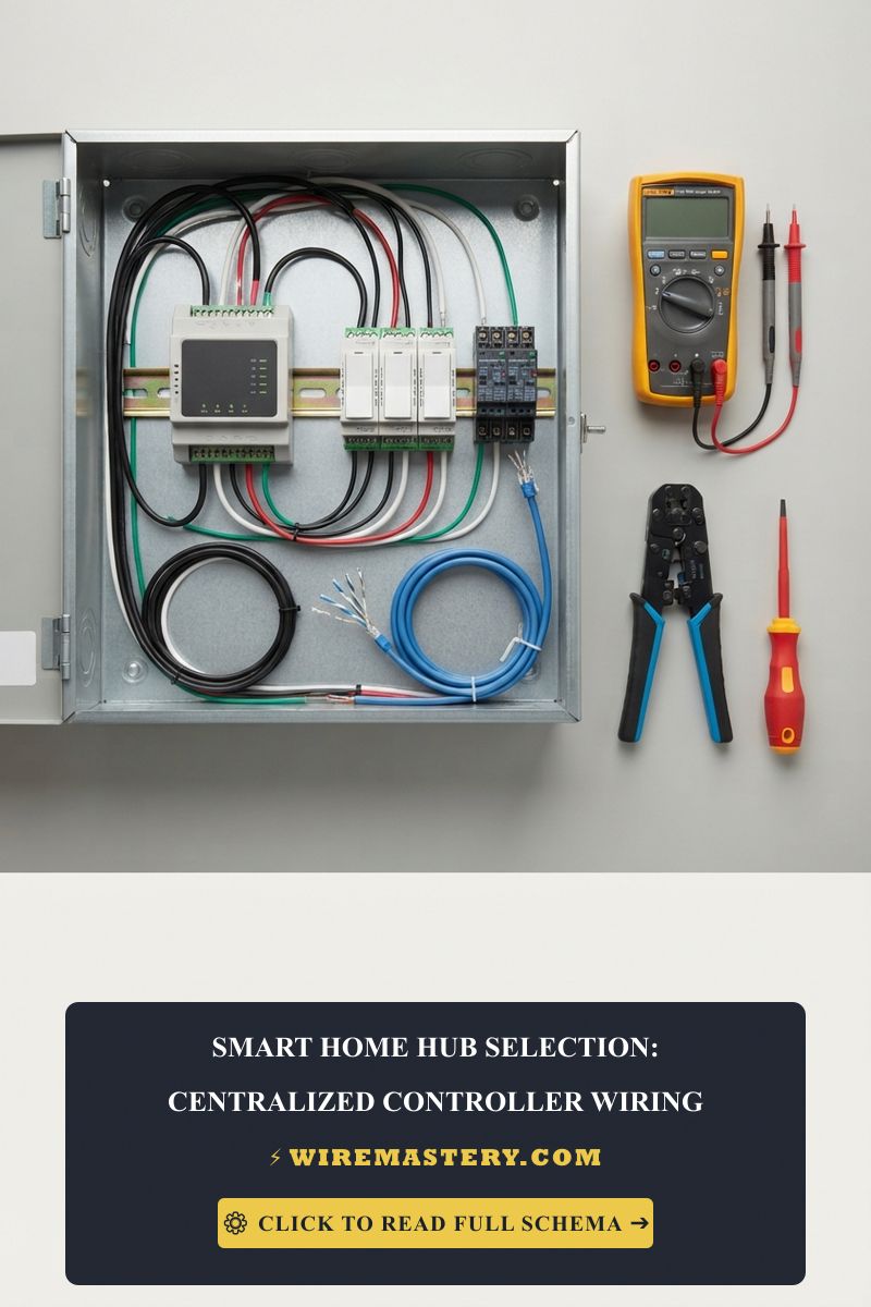
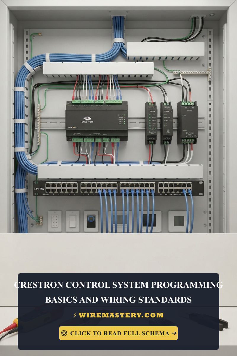
🛠️ Infrastructure Grounding Warning: Look closely at the industrial equipment layouts displayed inside modern automated command racks. Notice that all communication cables feature a silver drain shield wire. When terminating 4-pin Cresnet connections, you must bond this bare drain shield wire exclusively to the G (GND) terminal screw pin. Leaving the shield unbonded turns your control cable into a massive radio antenna that absorbs structural electromagnetic interference (EMI), mangling the digital square waves of your data lines and triggering intermittent system dropouts.
Step-by-Step Network Connectivity Recovery Blueprint
1. Pre-Diagnostic Energy Isolation
Before pulling heavy automation processors or switches out of an equipment rack casing, navigate to your property’s main network power panel block. Disengage the specific power supplies feeding the target hardware and use your non-contact tester to confirm that surrounding high-voltage power conduits read completely dead (0V AC).
2. Conducting the Live Voltmeter Bus Audit
If dealing with an offline device connected via a multi-conductor Cresnet cable, execute this precise voltmeter test sequence before altering any logic code files:
- Set your digital multimeter dial to DC Voltage mode (V_avg).
- Place your black probe onto the Black (GND) terminal screw and place your red probe onto the Red (+24) terminal screw. Note the digital display readout.
- Analyze the Multi-Tester Parameters:
- If the meter reads below +22V DC: The line suffers from a severe voltage drop or power supply starvation. You must upscale the wire gauge thickness or integrate an external auxiliary power module immediately.
- If the meter reads exactly +24V DC: The raw power delivery loop is flawless. Move your probes to test the White (Data +) and Blue (Data -) pins to confirm active digital communication pulse waves are generating.
3. Resolving IP Table and Firmware Mismatches
- Open Crestron Toolbox and launch the Text Console interface module.
- Type
ping [target_device_ip]to verify that the local TCP/IP network route is completely clear and open. - If the device responds to ping requests but remains completely offline inside your automation logic layout, type
remipid [IPID_code]followed byaddipid [IPID_code] [target_IP]. This command forces a clean reset of the internal routing tables, rebuilding the virtual communication bridge between the display faceplate and the central controller chip.
Troubleshooting Common Network Automation Failures
- The Processor Drops Offline Every Day at the Same Time: This is a classic symptom of an IP conflict or DHCP lease timeout dropout. If your network switch assigns the processor’s IP address to a laptop or secondary appliance via automated DHCP rules, the communication grid collapses instantly. Always map out a permanent Static IP address reservation outside your standard dynamic network pools for all primary automation hardware.
- The Controller Overheats and Tripps Thermal Lockouts: Check your equipment rack ventilation fans. High-performance multi-room processors generate continuous internal thermal currents. If dust mounds clog the ventilation slots or if multiple amplifiers are stacked tight against the unit casing without dynamic airflow loops, the chip will shut down immediately to protect its internal silicon architecture.
- Serial Terminal Control Strings are Scrambled or Unreadable: Indicates a grounding loop imbalance or an incorrect baud rate setting inside your SIMPL Windows compilation file. Ensure your serial cable lengths stay below 50 feet for standard RS-232 communication lines, and use a dedicated signal grounding track to isolate data loops cleanly from structural frame currents.
National Electrical Code Automation Safety Regulations
Adhering to strict national structural regulations protects your enterprise investments from damage and ensures full property insurance compliance. The National Electrical Code strictly regulates commercial automation grids and low-voltage remote-control lines under NEC Article 725 - Remote-Control, Signaling, and Power-Limited Circuits:
- Class 2 Short-Circuit Protective Boundaries: Automation data networks operate as low-voltage Class 2 signal lines. The NEC mandates that these systems must maintain full physical isolation thresholds to prevent high-voltage branch power lines from inducing massive electrical currents across sensitive data tracks during an insulation breakdown event, completely mitigating fire risks inside finished walls.
- Separation of Circuits (NEC 725.136): All Class 2 low-voltage communication and control cabling must maintain a minimum 2-inch clear physical separation from any high-voltage 120V/240V main branch power lines inside electrical boxes, conduits, and equipment enclosures unless separated by approved barriers, preventing severe electromagnetic cross-talk.
For the NFPA 70 provisions relevant to this guide on Crestron Support: Troubleshooting Network & Blank Screen Faults, consult the Official NFPA 70: National Electrical Code (NEC).
Conclusion
This article explains Crestron support parameters and executing low-voltage hardware circuit repairs transforms complex network dropouts into clean, systematic solutions. By resolving power budget bus overloads, clearing out blocked data transmission channels using precise voltmeter diagnostic sequences, and running low-level console scripts via terminal connections, you achieve a professional, automation network frame. For final checks, complete electrical power isolation testing, utilize certified diagnostic instruments, and execute every terminal step with code-compliant care.