Heavy-Duty Receptacle Installation: Wiring 240V NEMA Outlets
Engineering a code-compliant, high-voltage appliance circuit upgrade or executing a complete heavy-duty receptacle installation demands a rigorous operational command of dual-phase line-to-line voltage matrices, high-amperage continuous loading variables, and structural equipment grounding evolution. Unlike standard single-phase 120V convenience outlets that feed low-density household devices, modern heavy-duty residential appliances—such as electric clothes dryers, high-output cooking ranges, and rapid level-2 electric vehicle supply equipment (EVSE)—operate on a split-phase 208V/240V AC electrical framework. This high-energy system coordinates two individual, synchronized live hot phases simultaneously alongside dedicated neutral and ground paths, demanding flawless mechanical compression at each terminal lug to suppress high-resistance arc faults. Bypassing modern grounding isolation standards when rewiring these outlets introduces catastrophic shock and fire tracks behind finished wall framing.
This reference manual despatches the step-by-step layout configurations for NEMA 14-30R and 14-50R enclosures, the structural equations for calculating load ampacities, and professional high-voltage auditing toolkits.
Core High-Voltage Infrastructure Sizing Parameters
Before preparing heavy multi-conductor feeders or opening subpanel deadfront enclosures, decode these essential code boundaries:
- The 4-Wire Infrastructure Mandate (NEC 250.140): For decades under legacy code guidelines, residential building frameworks legally deployed a 3-wire branch circuit configuration (two hots and one neutral, using the uninsulated frame as a combined neutral-ground path) to power clothes dryers and cooking ranges. Modern National Electrical Code updates strictly ban this practice for all new installations and modifications. Current regulations mandate an explicit 4-wire circuit matrix incorporating independent Grounded Neutral (White) and Equipment Grounding (Bare/Green) paths, fully preventing return currents from polarizing the appliance metal chassis frame.
- NEMA 14-30R Configuration Parameters: The standard field specification reserved exclusively for electric clothes dryers. Sized for a nominal rating of 30 Amps at 125V/250V AC, this configuration requires a dedicated dual-pole breaker center loop.
- NEMA 14-50R Configuration Parameters: The universal standard for high-draw residential cooking ranges and level-2 residential EVSE basins. Sized to sustain continuous currents up to 50 Amps nominal continuous, this hardware assembly demands robust structural clearances inside deep junction boxes to handle thick wire bend parameters.
Technical Materials & High-Amperage 240V Auditing Toolkit Checklist
Safely opening high-energy subpanel enclosures and securing thick-gauge terminal lugs requires specialized diagnostic instrumentation and 1000V-rated insulated tools:
| Industrial Splicing Tool | Primary Engineering Purpose & Trade Safety Rating |
|---|---|
| True RMS Digital Clamp Meter | Category CAT III 600V certified to safely capture continuous 240V running currents. |
| Calibrated Dial Torque Wrench | Absolute legal requirement to tighten heavy-duty terminal lugs to exact inch-pound specs. |
| Non-Contact AC Proximity Tester | Proximity sensor to audibly guarantee 100% bus de-energization before wire handling. |
| High-Leverage Cable Shear Cutters | Hardened jaws to cut through thick #10, #8, and #6 AWG copper conductor shanks cleanly. |
| Class 00 Dielectric Rubber Gloves | High-density rubber insulation rated to isolate hands from up to 500V AC continuous. |
Conductor Profiles & High-Amperage Load Constraints (NEC Table 310.16)
Attempting to run a heavy-duty 240V appliance circuit over thin, standard residential convenience wires will instantly vaporize the insulation wraps. Installers match conductor diameters directly to the overcurrent limit enforced under NEC Article 310.16 parameters:
- 10 AWG Four-Conductor Cable (14-30R / 30-Amp Circuit Limit): Encased within an orange PVC NM-B Romex jacket sheath. Houses two independent hot lines (Black and Red), one solid grounded neutral (White), and one bare copper equipment ground wire. Mandatory infrastructure size to supply residential electric dryers safely.
- 8 AWG Four-Conductor Cable (40-Amp Circuit Limit): Heavy-duty branch profile. Sized for smaller electric range assemblies. Features stranded conductor cores to facilitate structural routing inside tight framing cavities.
- 6 AWG Four-Conductor Cable (14-50R / 50-Amp Circuit Limit): The absolute trade standard for high-output electric ranges and continuous EVSE level-2 vehicle charging networks. Requires thick #6 AWG copper THHN strands running inside a rigid conduit track or heavy sheathed service bundles, sustaining a continuous 40-Amp loading draw safely without thermal wire decay.
Step-by-Step Field Blueprint: Wiring NEMA 14-30R & 14-50R Enclosures
To execute a flawless, code-compliant high-voltage installation matching the strict grounding isolation laws of modern building regulations, apply this systematic field trade sequence:
1. Pre-Installation Overcurrent Energy Isolation
Navigate to your property’s primary service distribution panel board. Identify and disengage the dedicated 30-Amp or 50-Amp dual-pole circuit breaker assigned to the heavy appliance branch. Lock out the toggle handle using your padlock tagout clamp. Move to the wall workstation box cavity, remove the faceplate screws, and press your non-contact tester against all internal components to confirm an absolute 0V AC state before handling the conductor ends.
2. Terminating the 4-Wire High-Voltage Terminal Blocks
Because #10 AWG and #6 AWG conductors possess immense physical stiffness, you must utilize deep 4-inch square metallic or heavy-duty thermoplastic junction box enclosures equipped with extension rings to provide ample wire-bending space.
- Strip exactly 5/8 inch of insulation off your heavy solid or stranded copper wire cores using your precision cable strippers. Ensure the exposed copper strands are straight and clean.
- Take your new NEMA 14-30R or 14-50R device yoke. Insert the conductor tips deep into the assigned rear pressure-plate terminal slots following the explicit mechanical mapping stamped on the device mold:
- The L1 Phase (Line Hot): Insert the Black wire into the side terminal screw slot marked Y or L1.
- The L2 Phase (Line Hot): Insert the Red wire into the opposing side terminal screw slot marked X or L2.
- The Grounded Neutral: Insert the White wire into the upper terminal screw slot marked W or White.
- The Equipment Ground: Insert the Bare copper or Green wire into the bottom semicircular terminal port marked G or Ground.
- The Compressive Torque Directive (NEC 110.14(D)): High-amperage current loops generate intensive thermal expansion stress cycles. You must deploy a calibrated torque wrench to tighten the terminal pressure plate screws to the exact manufacturer engineering specs stamped on the device mold (typically 45 to 55 inch-pounds), preventing loose connections that lead to catastrophic arc faults.
3. Modifying the Appliance Cord Link (The Grounding Bond Swap)
When upgrading a property’s wall receptacle from an ungrounded 3-wire system to a modern 4-wire NEMA 14-30R/14-50R grid, you are legally required to alter the connection profile inside the appliance termination box (back of the dryer or stove):
- Remove the metal access shield plate on the rear of the appliance casing.
- Unscrew and discard the factory-installed copper bonding strap or green wire link that bridges the center silver neutral terminal block straight onto the green grounded sheet-metal appliance chassis frame. Leaving this strap intact inside a 4-wire network shorts your neutral and ground wires in parallel down the line, a severe code violation.
- Install a brand-new, certified 4-prong heavy-duty appliance cord harness. Connect the Black hot to outer brass, Red hot to outer brass, White neutral to center silver, and screw the independent Green ground wire loop directly onto the green grounding hex screw driven into the appliance metal frame, fully isolating the paths.
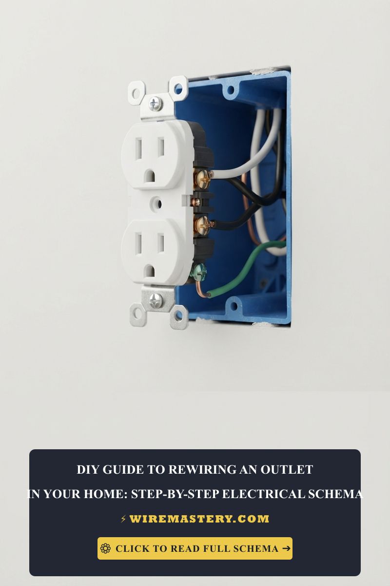
🛠️ Deep Box Volume Headroom Note: Look closely at the industrial high-voltage component specifications printed across our structural installation manuals. Notice that packing four thick #6 AWG current-carrying conductors and a bulky 50-Amp NEMA 14-50R device yoke into a shallow wall cavity single-gang box is completely illegal. Under the strict calculation matrices of NEC 314.16(B), every single #6 AWG wire landing inside an enclosure demands a massive 5.00 cubic inches of free space volume, while the 50A receptacle yoke mandates a double conductor volume deduction based on the supplying wire size, requiring a minimum 42-cubic-inch deep 4x4-inch box enclosure to block wire-pinching short circuits.
Troubleshooting Common Heavy-Duty Appliance Circuit Failures
- The Dryer Drum Spins and Timer Counts, but the Element Never Generates Heat: This specific operational failure indicates an active Single-Phasing dropout or a tripped half-pole breaker phase. The low-voltage digital controls and clock motors inside a 125V/250V appliance operate on a single 120V phase phase relative to neutral (L1-to-N). However, the massive high-wattage resistive heating element blocks require a full 240V potential difference across both hot phases combined (L1-to-L2). Connect your multimeter in AC voltage mode across L1 and L2 slots; if the meter registers 0V but reads 120V from each slot independently to neutral, one of your subpanel breaker phases has suffered internal contact degradation, requiring immediate replacement.
- The Main Dual-Pole Circuit Breaker Trips Immediately Upon Appliance Power Activation: An absolute indicator of a Dead Short Circuit or an uninsulated grounding pinch hazard. This occurs when an apprentice installer forces the stiff #6 AWG or #10 AWG wire bundles into a tight box enclosure haphazardly, causing an uninsulated bare copper grounding wire to press tight against a live side brass phase terminal screw plate. Pull the device out using your insulated panel tools, wrap the entire perimeter of the outlet casing with two tight layers of high-grade 600V-rated electrical tape to provide an unshakeable insulation barrier, and accordion-fold the wires flat against the box rear wall.
- The NEMA Outlet Faceplate Discolors or Emits an Acrid Plastic Smell: An absolute indicator of a High-Resistance Connection or an Under-Torqued Lug screw fault. If a terminal screw plate was tightened by hand without utilizing a calibrated dial torque tool, the stranded copper filaments will spread under thermal loading, inducing continuous micro-arcing. This resistance converts current into intense localized thermal heat, melting the nylon housing. Cut back the scorched conductor tips and install a new terminal block under rigid torque controls.
National Electrical Code High-Voltage Safety Enforcements
Adhering to strict national installation codes protects your home electronics investment, maintains property valuation, and ensures full property insurance compliance. The National Electrical Code strictly regulates high-amperage appliances, grounding systems, and receptacle boundaries under NEC Article 250 (Grounding and Bonding) and Article 406 (Receptacles):
- The Grounding Isolation Requirement (NEC 250.142): Grounding conductors shall not be used as a current-carrying return path for electronic controls or neutral phases down the line of the primary service disconnecting means panel board center. Heavy-duty appliances must separate neutral and grounding pathways completely to eliminate structural chassis electrification hazards.
- Receptacle Rating Boundaries (NEC 406.3): Receptacles shall be isolated and selected strictly to match the nominal branch overcurrent protection device rating. Installing a 50-Amp NEMA 14-50R outlet onto a branch line protected via a thin 30-Amp circuit breaker violates federal code compliance inspection metrics, creating Direct overloading hazards.
For the NFPA 70 provisions relevant to this guide on Heavy-Duty Receptacle Installation: Wiring 240V NEMA Outlets, consult the Official NFPA 70: National Electrical Code (NEC).
Conclusion
This guide covers calculating split-phase 240V dual-line current values, isolating ungrounded neutral tracks from equipment safety grounding lines through code-compliant 4-wire NEMA topographies, and executing precise terminal lug compression settings using calibrated torque wrenches transforms complex heavy appliance wiring upgrades into highly predictable solutions. By keeping branch conductor gauges fully aligned with NEC Article 310.16 overcurrent charts, eliminating hazardous chassis electrification links on appliance frames, and enforcing strict compliance with NEC Article 314 box fill clearances, you build an exceptionally resilient, safe residential grid infrastructure. For final checks, complete panel breaker power isolation safety checkups before opening junction enclosures, deploy CAT III certified True RMS meters, and execute every high-voltage termination step with safety-first precision.







