Electric Panel Upgrade: Residential Load Calculation Math
Engineering a code-compliant, residential electric panel upgrade or sizing a master service entrance infrastructure requires an advanced structural command of load diversity factors, thermal bus bar thermodynamics, and non-continuous vs. continuous circuit parameters. In North American residential construction, sizing an electrical panel board enclosure cannot depend on simplistic wattage summation formulas. Modern properties heavily integrated with localized electric vehicle supply equipment (EVSE), instantaneous tankless hot water matrices, and high-inductance heat pump systems demand rigorous analytical sizing. Applying crude calculations without enforcing demand factor reductions yields flawed engineering metrics, causing either hazardous main disconnect bus bar overheating loops or unnecessary service upscaling expenses.
This reference manual despatches the precise mathematical equations for NEC Article 220 residential load calculations, service entrance ampacity thresholds, and advanced on-site diagnostic metrology toolkits.
Core Service Sizing Engineering Thresholds
Before removing factory enclosure plates or landing heavy service feeder lines onto primary main lugs, decode these foundational parameters:
- The 80% Continuous Loading Boundary: Under the strict mandates of NEC Article 210.20, any electrical load running uninterrupted for 3 hours or more (such as space heating layouts or continuous vehicle charging basins) is classified as a continuous load. Branch conductors and supplying circuit breakers must be sized at 125% of the nominal continuous current draw, ensuring ample thermal headroom inside the panel gutters.
- The 100-Amp Minimum Infrastructure Floor (NEC 230.79): The National Electrical Code enforces an absolute legal minimum rating of 100 Amps, 3-wire service for any single-family residential dwelling unit. This baseline is strictly reserved for legacy structures with minimal footprint metrics and non-electric heating configurations.
- The Neutral-Ground Main Bonding Mandate: Within the primary service panel board enclosure exclusively, the grounded neutral bus bar and the equipment grounding conductor rail must be physically linked via an unspliced green main bonding jumper screw. This explicit connection point establishes a low-impedance ground-fault current path, allowing upstream protection devices to trip instantly during an active terminal short circuit blowout.
Technical Materials & High-Energy Subpanel Auditing Toolkit
Safely backing out enclosure deadfront shields and testing energized main service entrance lugs requires specialized high-dielectric field tools and testing instrumentation:
| Industrial Auditing Tool | Primary Engineering Purpose & Safety Certification |
|---|---|
| True RMS CAT IV Clamp Meter | Category CAT IV 600V certified to capture live service entrance currents safely. |
| Non-Contact AC Proximity Tester | High-sensitivity sensor to audibly guarantee 100% bus de-energization before wire handling. |
| 1000V Insulated Torque Wrench | Calibrated to torque modern panel main lugs to exact inch-pound specs. |
| Infrared Thermal Laser Scanner | Maps active thermal hotspots across breaker casings from a safe distance without contact. |
| Class 00 Dielectric Rubber Gloves | High-density protective gloves rated to block up to 500V AC continuous contact tracks. |
Service Entrance Conductor Gauges & Ampacity Benchmarks (NEC Table 310.12)
A core professional trade competency required to engineer an electrical panel board upgrade safely is matching the conductor metallurgy cross-sectional circular mil area to the primary overcurrent protection device limit:
- 100-Amp Service Panel Configuration: Deployed exclusively for small apartments or compact single-family units utilizing gas heating layouts. Requires a minimum conductor size of #4 AWG copper THWN strands or #2 AWG aluminum lines enclosed within a rigid conduit run.
- 200-Amp Service Panel Configuration: The modern residential standard for comprehensive home additions and automated smart home layouts. Demands an upscale to 2/0 (Two-Ought) AWG copper lines or 4/0 (Four-Ought) AWG aluminum conductor lines to eliminate progressive voltage dropouts under concurrent appliance startups.
- 400-Amp Service Panel Configuration: Engineered for custom estate properties, dual luxury EVSE matrices, or properties executing intensive geo-thermal space heating setups. Mandates the installation of 400 kcmil (thousand circular mils) copper conductors or dual-paralleled 3/0 AWG copper feeder branches running inside separate conduit raceways.
Technical Phase 2: Mastering the Step-by-Step NEC Article 220 Load Calculation
To size an electric panel upgrade or verify if a residential service can legally absorb new automated hardware infrastructure additions without experiencing dangerous voltage drops, engineers reject casual wattage guesses and apply the strict NEC Article 220 Standard Calculation Method:
Step 1: General Lighting and Receptacle VA Load Allocation
- Calculate Square Footage Area: Measure the gross exterior dimensions of the residential structure. Multiply the total square footage by the standard NEC factor of 3 Volt-Amperes (VA) per square foot (derived from NEC Table 220.12) to determine your baseline lighting and convenience branch circuit load.
- Add Kitchen and Laundry Small Appliance Branch Circuits (SABC): Under NEC 220.52, you must add a fixed allocation of 1,500 VA for each of the two mandatory kitchen small appliance circuits, plus an additional 1,500 VA for the dedicated laundry branch circuit, totaling a baseline structural anchor of 4,500 VA.
- Apply the General Demand Diversity Factor (NEC Table 220.42): Sum the square footage VA and the 4,500 VA SABC allocation together. Apply the standard diversity multipliers:
- Take the first 3,000 VA of the cumulative sum at 100% full demand factor.
- Take the remaining portion floating between 3,001 VA and 120,000 VA at a reduced 35% demand factor. Note this adjusted subtotal.
Step 2: Fixed Appliance Nameplate Compilation
Sum the exact nameplate kilowatt (kW) ratings of all fixed mechanical appliances that do not cycle concurrently under the provisions of NEC 220.53:
- Compile Appliances: Include the dedicated water heater element blocks, garbage disposals, dishwashers, and electric clothes dryers at 100% of their individual nameplate parameters.
- Apply the Four-Appliance Rule: If the property houses four or more fixed appliances in parallel, you are legally permitted to apply a 75% demand factor reduction to the entire appliance subtotal, significantly shrinking your feeder requirements.
- Isolate Coincident Heating vs. Cooling Loads: Under NEC 220.60, compare the total non-coincident peak continuous loads of your central air conditioning compressor compressor array (NEC Article 440) against your electric resistance space-heating coils. Discard the smaller value entirely from the calculation matrix, as both systems will never run simultaneously.
Step 3: Extracting the Final Service Entrance Ampacity Floor
-
Sum your diversified general lighting subtotal, your appliance subtotal, and your dominant HVAC load parameter together to find the true net calculated Volt-Amperes (VA_net).
-
Execute the Single-Phase Amperage Conversion: Divide the net calculated VA value by the standard single-phase nominal line-to-line utility potential of 240 Volts:
Total Service Amperage = Net Calculated VA (VA_net) / 240V
-
The resulting amperage parameter dictates your exact minimum service upgrade scale. If the final number evaluates to 142 Amps, you must upscale past standard 150A hardware blocks and install a certified 200-Amp master distribution panel center to ensure proper engineering safety margin clearance.
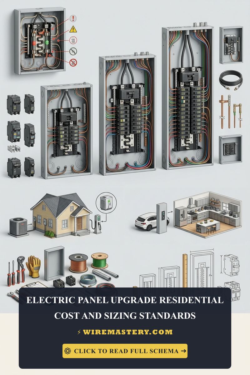
🛠️ Main Breaker vs. Main Lug Enclosure Note: Look closely at the split-phase service panels showcased across our electrical layout portfolios. Notice the distinction between a Main Breaker Panel (which houses an integrated primary 200A master overcurrent disconnect switch that kills power to the entire bus bar array) and a Main Lug Only (MLO) Panel (which lacks an integrated switch and relies on an upstream external breaker to cut power). When executing a residential service entrance upgrade, your primary panel box must be a certified Main Breaker enclosure to serve as the legal, readily accessible single disconnecting means mandated by building safety regulations.
Troubleshooting Post-Upgrade Subpanel Anomalies
- The Main Breaker Emits a Loud Hum Under Balanced Loads: This indicates a severe compressive jaw seating deficit or microscopic loose play along the panel bus bar tab intersection. Modern plug-on circuit breakers utilize heavy spring clips to grip the hot bus rails. If an installer fails to snap the breaker chassis down square and flush, micro-air gaps form. Alternating current at 60 Hz induces mechanical chattering across these loose clips, generating heat that will pit the bus metal. Pull the breaker and re-seat the jaws using insulated panel tools.
- The Newly Installed AFCI Breakers Trip Instantly Upon Panel Initialization: An absolute indicator of an active downstream neutral-to-ground wire pinch executed during the downstream branch re-packing phase. While legacy panels with old thermal breakers were completely blind to micro-ampere leakage paths, a modern Arc-Fault (AFCI) or GFCI breaker uses internal solid-state current transformers to monitor line balances. If a white neutral wire touches a bare ground wire inside a tight gang box, the breaker drops the line offline instantly. Run unpowered resistance continuity tests to isolate the short circuit box by box.
- The Main Panel Main Lugs Register Over 140°F (60°C) Under Thermal Sweeps: An absolute indicator of aluminum conductor cold-flow loosening or an anti-oxidant omission fault. Aluminum service conductors naturally expand and cold-flow under seasonal thermal cycles. If the installer failed to use a calibrated torque wrench to torque the main lugs to exact manufacturer inch-pound specs, the terminal loosens, multiplying terminal resistance. Isolate the meter power immediately and torque the lugs down to specifications.
National Electrical Code Subpanel Clearance Enforcements
Adhering to strict national structural regulations protects your home infrastructure from electrical fire hazards, maintains full property insurance validity, and ensures complete alignment with federal inspection safety boundaries. The National Electrical Code strictly regulates residential service panels, working spaces, and enclosure locations under NEC Article 110 (Requirements for Electrical Installations) and Article 408 (Switchboards and Panelboards):
- The Working Clearance Spatial Envelope (NEC 110.26): Main circuit breaker panels and relocated subpanel gutters must maintain an absolute, un-obstructed physical clear working area of at least 3 feet (36 inches) of front depth clearance and 30 inches of flat width clearance from the deadfront shield. This spatial envelope must extend from the finished floor plane up to a minimal height of 6.5 feet, ensuring field service technicians maintain ample free breathing space to access components safely.
- The Prohibited Room Mandate (NEC 240.24): Circuit breakers and distribution panel boards are strictly prohibited from being located inside residential clothes closets packed with easily ignitible fabrics, or within high-moisture residential bathrooms, preventing immediate component corrosion and arc-flash fire escalation hazards.
For the NFPA 70 provisions relevant to this guide on Electric Panel Upgrade: Residential Load Calculation Math, consult the Official NFPA 70: National Electrical Code (NEC).
Conclusion
This guide covers executing rigid NEC Article 220 load calculation matrices, applying standard demand diversity factor reductions, and upscaling service entrance conductor diameters under NEC Table 310.12 parameters transforms complex electrical panel upgrades into safe, highly controlled residential engineering operations. By keeping thermal heat dissipation within strict continuous overcurrent protection limits, enforcing separate ground-neutral bus bar insulation paths inside downstream subpanel enclosures, and respecting mandatory NEC workspace clearance boundaries, you build an exceptionally resilient, safe home grid infrastructure. For final checks, complete main utility disconnect safety checks before raw line handling, deploy CAT IV certified digital clamp meters, and complete every mechanical terminal connection step with precision.







