Electrical Contractor Certification: License Requirements & Training Manual
Navigating the path from an entry-level electrical apprentice to a licensed journeyman or certified master contractor demands a strict compliance overview of state board parameters, technical training hours, and rigorous code examinations. Within professional trade industries across the United States, obtaining official credentials represents the primary operational boundary separating unregulated labor from authorized multi-phase infrastructure execution. Industrial engineering projects, commercial switchgear installations, and residential developments cannot legally proceed without a certified professional anchoring the utility permits.
To ensure long-term career growth and preserve full compliance lines across physical footprints, systems integrators abandon shortcut learning processes. They bind their professional training directly to structured vocational pathways and master national safety parameters before sitting for municipal trade board evaluations.
Structural Phases of the Professional Licensing Matrix
Earning a state-recognized credential requires satisfying distinct practical experience thresholds and academic credit baselines verified by local departments of labor:
- The Registered Apprenticeship Phase: The foundational baseline of the trade. Candidates complete a minimum of 4 years (8,000 hours) of supervised on-the-job training, paired with at least 576 hours of classroom-based technical instruction. Apprentices focus on standard raceway installations, circuit layout blueprints, and branch load balance calculations under direct journeyman supervision.
- The Journeyman Electrician Standard: Upon completing the field apprenticeship matrix, installers sit for the official state Journeyman examination. This credential unlocks the legal authority to route commercial distribution lines, execute subpanel splices, and perform live system maintenance independently without direct oversight.
- The Master Contractor Classification: The pinnacle designation of industrial trade tracks. Requiring an additional 2 to 4 years of continuous Journeyman execution experience, candidates must pass a multi-part advanced examination covering structural transformer design math, heavy microgrid load calculations, and business law regulations.
Technical Materials & Examination Auditing Toolkit
Successfully passing a state trade examination requires a complete command of physical reference handbooks and specialized technical calculators:
| Examination Testing Material | Primary Engineering Purpose & Trade Target Metric |
|---|---|
| Official NFPA 70 Handbook | The core regulatory text allowed inside open-book state licensing evaluation centers. |
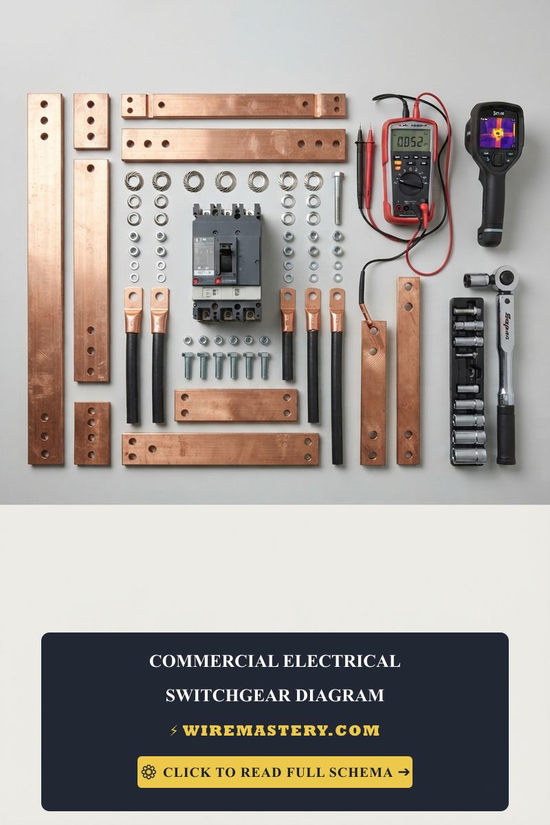
| True RMS Industrial Multimeter | Diagnostic tool utilized during practical laboratory wiring exam performance sweeps. |
| Calibrated Dial Torque Wrench | Used to demonstrate precise code compliance under terminal lug torque regulations. |
| Insulated Hand Tool Set (1000V) | Mandatory safety gear verified during practical field commissioning test modules. |
| Non-Linear Load Power Quality Analyzer | Advanced instrumentation mapped across complex commercial contractor test simulations. |
Advanced Exam Calculations: Mastering Code Math
To pass the state examination, candidates must execute complex electrical formulas under tight time constraints with zero margin for error. The math focus centers on core sizing protocols:
1. The Standard Service Load Calculation Sequence (NEC Article 220)
Before sizing a main service entrance panel board, an engineer must compute the true diversified demand load of the residential or commercial facility.
- General Lighting Load: Calculate the floor area square footage and multiply by 3 Volt-Amperes per square foot for residential units.
- Small Appliance and Laundry Branches: Add a fixed apparent load of 1,500 VA for each dedicated kitchen small appliance branch circuit (minimum of two required by code) and another 1,500 VA for the laundry circuit.
- Apply Demand Diversity Multipliers (NEC Table 220.42): The first 3,000 VA of the combined general load is taken at 100% load allocation. The remaining balance between 3,001 VA and 120,000 VA is reduced using a 35% demand multiplier, reflecting that all lights and outlets never operate concurrently.
2. Motor Branch and Overcurrent Protection Sizing (NEC Article 430)
Unlike standard resistive lighting loads, industrial electric motors draw severe current surges during locked-rotor starting states.
- Conductor Sizing: Feeders supplying a single continuous-duty motor must carry an ampacity rating of at least 125% of the motor’s Full-Load Amperage (FLA) nameplate value to prevent wire insulation jacket breakdown under heavy heat.
- Short-Circuit Protection: To clear hazardous dead shorts without causing nuisance thermal trips during startup bursts, inverse-time circuit breakers are allowed to upscale up to 250% of the motor FLA rating, relying on downstream thermal overloads to manage progressive thermal decay.
Technical Phase 2: Practical Lab Wiring & Field Auditing Simulations
The practical laboratory portion of the contractor examination forces the technician to transform flat schematic drafting blueprints into code-compliant physical assets within an interactive testing booth enclosure.
1. Step-by-Step Practical Board Assembly Sequence
When executing a commercial three-way lighting loop or a multi-phase motor starter control circuit under the eyes of state trade board inspectors, follow this rigid sequence:
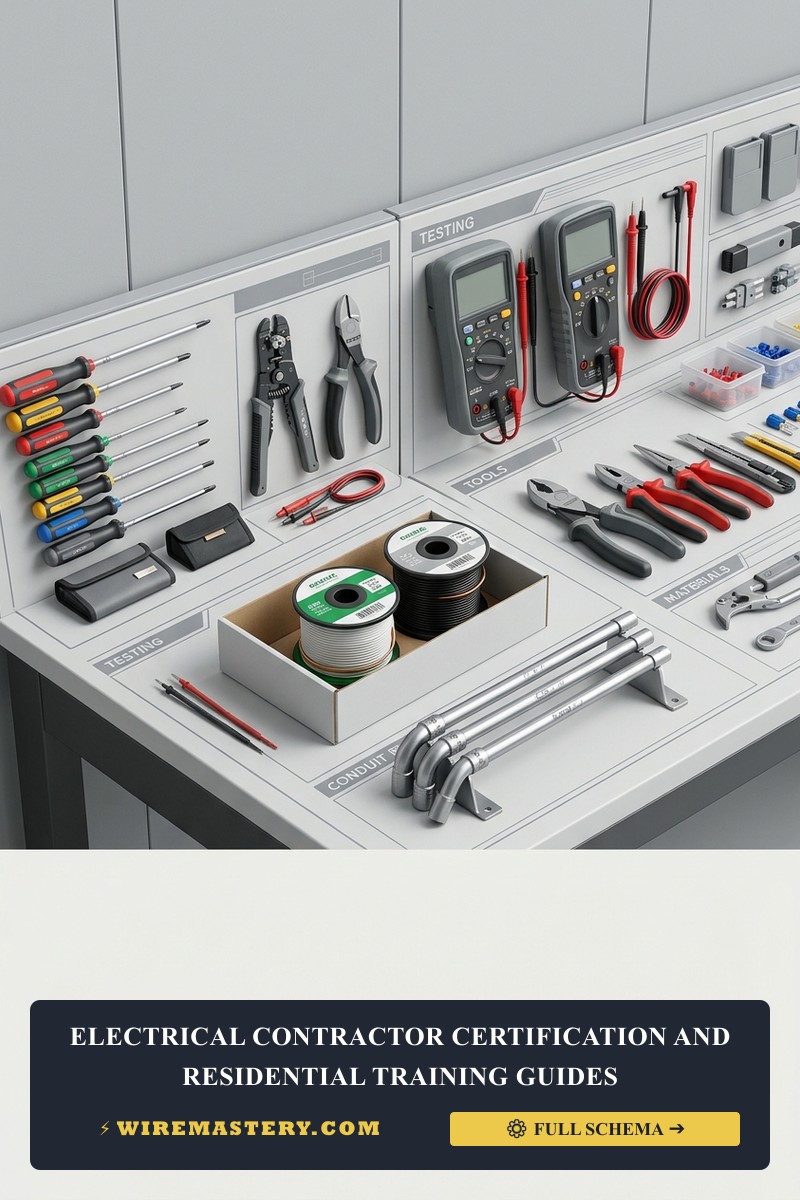
- Mount the Enclosure Boxes and Conduit Tracks: Secure your metallic single-gang boxes and deep four-inch square junction enclosures onto the testing backboard panel. Route a length of 1/2-inch Electrical Metallic Tubing (EMT) between the boxes, pulling clean wires using a fiberglass fish tape tool.
- Execute the 360-Degree Bend Check (NEC 358.26): Ensure that the cumulative sum of all bends in the conduit run between pull boxes does not exceed four 90-degree bends (360 degrees total). Exceeding this limit causes extreme friction during wire pulls, shearing the protective nylon slick sheaths off the THHN copper strands.
- Establish Solid Equipment Grounding Paths: Grounding boundaries are absolute. Bond the bare or green safety grounding conductors directly to the metallic box frame using a green hex grounding screw plate before splicing the ground wires together. This solid ground connection ensures fault currents travel straight to earth, tripping the breaker immediately instead of energizing the metal box deadfronts.
National Electrical Safety Code Commercial Switchgear Enforcements
Adhering to strict national installation codes and industrial safety parameters shields your commercial operations from liability, maintains full corporate insurance compliance, and protects field workers from arc-flash blast trajectories. Industrial training matrices are heavily cross-regulated under NFPA 70E (Standard for Electrical Safety in the Workplace) and NEC Article 230:
- The Arc-Flash Hazard Warning Boundary (NFPA 70E 130.5): All commercial switchgear units, industrial panel boards, motor control centers, and heavy disconnect box enclosures mapped across your industrial electrical schematic prints must carry a permanent, highly visible field warning label. This sticker must specify the exact nominal system potential, the calculated arc-flash incident energy level (measured in calories per square centimeter), the precise flash protection boundary distance, and the mandatory level of personal protective equipment (PPE) required before opening the protective metal housing deadfronts.
- The Single Main Service Disconnect Rule (NEC 230.71): Current commercial electrical building codes dictate that each independent building facility electrical service infrastructure shall be equipped with a unified, centralized single main disconnect switch mechanism to isolate the complete grid potential in a single motion. This master breaker layout must be explicitly highlighted on all main single line diagram schematics to give emergency response teams an immediate shutdown pathway during structural incidents.
For the NFPA 70 provisions relevant to this guide on Electrical Contractor Certification: License Requirements & Training Manual, consult the Official NFPA 70: National Electrical Code (NEC).