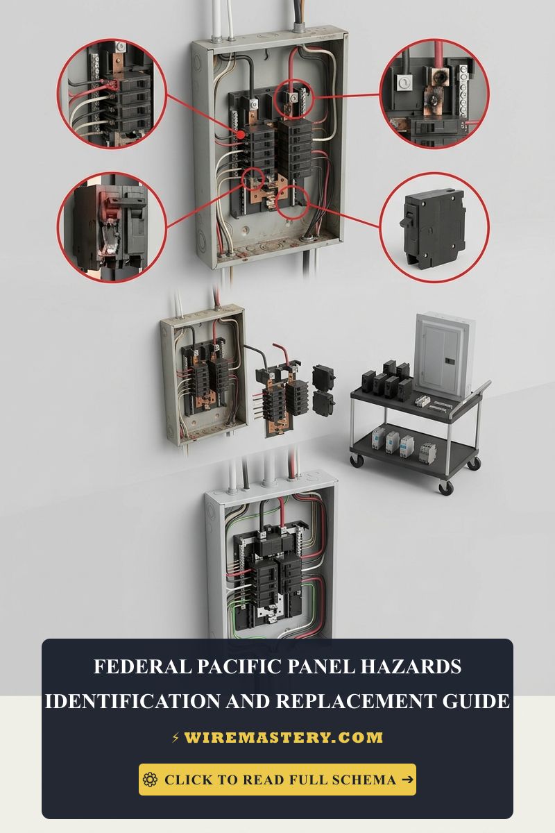
Federal Pacific Panel Hazards: Contractor Replacement Guide
Architecting a structural engineering roadmap to identify and eliminate the latent fire liabilities associated with a legacy Federal Pacific Electric (FPE) Stab-Lok circuit breaker panel board is one of the most critical life-safety retrofits executed in North American residential property maintenance. Manufactured and installed across millions of housing footprints between the 1950s and the 1980s, these defective distribution hubs represent a documented fire hazard flagged systematically by electrical inspectors, home insurance underwriters, and the Consumer Product Safety Commission (CPSC). The underlying engineering failure is not a simple wear-and-tear degradation loop; it is a severe mechanical design defect within the plug-on breaker jaw assembly and bimetallic trip armatures that causes the breakers to freeze, locking out their safety capabilities during sustained overcurrent events.
This technical reference manual outlines the structural physics of Stab-Lok failures, professional identification protocols, and strict utility-level safety isolation frameworks.
Core FPE Metallurgical and Design Failure Points
Before authorizing a panel replacement schedule or probing internal bus structures, field engineers must fully understand the explicit mechanical fault modes native to FPE enclosures:
- The Non-Tripping Latch Failure (The Fire Vector): Under independent laboratory testing (including extensive CPSC engineering audits), FPE Stab-Lok dual-pole breakers exhibited an unmitigated failure-to-trip rate exceeding 25% to 60% under continuous overload currents. Instead of deflecting to isolate the branch line, the internal latch welds shut under thermal stress, siphoning massive currents continuously until the Romex conductor jackets melt inside the wall cavities.
- The Stab-In Bus Bar Arcing Pitfall: The proprietary “Stab-Lok” mechanical link relies on a thin metal prong on the breaker jaw that slides into a slotted opening on the panel’s central bus bar. Over continuous thermal cycles, this un-torqued friction connection loses its compressive grip, creating a micro-air gap that induces continuous high-temperature voltage arcing, pitting the bus metal and generating carbon soot tracks.
- The Ungrounded Structural Enclosure Enclosure Box Fill: Most vintage FPE gutters feature highly restrictive internal cubic-inch volumes, violating modern box fill spacing parameters under NEC Article 314. Forcing multiple high-density multi-conductor cables into these cramped spaces accelerates localized ambient air temperatures, triggering premature material breakdowns.
Technical Materials & Utility-Level Service Panel Toolkit
Safely verifying line potentials and executing major service entrance replacements requires industrial-grade testing instrumentation and specialized insulated hand tools:
| Industrial Electrical Tool | Primary Engineering Purpose & Safety Threshold |
|---|---|
| True RMS Digital Clamp Meter | Category CAT IV 600V certified to measure live main service lug currents safely. |
| Infrared Thermal Laser Scanner | Maps active thermal hotspots across breaker casings from a safe distance before disassembly. |
| 1000V Insulated Torque Wrench | Calibrated to torque modern panel main lugs to exact inch-pound building parameters. |
| Dual-Phase Non-Contact Tester | Proximity sensor to audibly guarantee 100% bus de-energization before quick-plug handling. |
| Personal Protective Gear (PPE) | Class 00 dielectric gloves, arc-flash face shields, and flame-resistant (FR) work layers. |
Service Entrance Conductor Profiles & Ampacity Ratings (NEC 310.16)
When engineering a complete panel service upgrade to replace a hazardous FPE footprint, you must size your new service entrance conductors and main service breakers to match the structural loading demands calculated under NEC Article 220 parameters:
- 100-Amp Master Panel Upgrade Baseline: Sized as the absolute legal minimum for small residential properties under modern building codes. Requires a minimum of #4 AWG copper THWN conductors or #2 AWG aluminum lines routed inside a rigid conduit track.
- 200-Amp Master Panel Upgrade Standard: The modern contractor standard for comprehensive residential home additions, automated home hubs, and vehicle charging configurations. Demands a minimum of 2/0 (Two-Ought) AWG copper lines or 4/0 (Four-Ought) AWG aluminum conductors to maintain complete line-voltage stability under peak load cycles.
Technical Phase 1: Visual Identification & Risk Screening Protocol
To determine with absolute certainty whether an existing residential structure houses a volatile FPE distribution system, a field technician executes this non-invasive 4-point visual audit:
1. External and Internal Branding Check
Examine the master service enclosure door panel faceplate cover. Look closely for the official embossed Federal Pacific Electric logo (a stylized “FPE” shield icon) or printed manufacturer text blocks reading “Federal Pacific Electric Company” or “Stab-Lok”.
2. Breaker Toggle and Casing Profiling
Open the panel door and evaluate the individual circuit breaker toggles. FPE Stab-Lok breakers feature highly distinct visual footprints: the toggle switches are typically wider than standard modern modules and are split down the center with contrasting color bands (often bright red, neon orange, or dull blue handles).
3. Thermal Tracking Audit
Do not touch internal components. Use your non-contact infrared thermal laser scanner to sweep the front faces of all active breaker handles. If individual breaker casing modules or the main chassis center register localized temperature readings exceeding 122°F (60°C) while drawing standard continuous currents well below their nominal rating, internal contact arcing is actively occurring, making a structural replacement urgent.
Technical Phase 2: Professional Service Disconnection & Panel Board Replacement
Replacing a hazardous Federal Pacific Electric panel board is a master-level utility service operation that must never be treated as a casual DIY home improvement task. Bypassing standard electrical safety layers risks triggering immediate arc-flash explosions.
1. The Critical Upstream Power Isolation Boundary (NEC Article 230)
The single most lethal mistake made during amateur panel changeovers is assuming that turning off the main 100A or 200A breaker de-energizes the entire enclosure.
- The Physics of the Hazard: The main service disconnect breaker only slices power to the branch bus bars down the line. The incoming lines trailing from the outdoor utility transformer drop straight onto the Main Service Lugs at the top of the panel, leaving them energized with a raw 240V potential continuously. Slicing into these lugs or dropping a tool across them will bypass all overcurrent protections, vaporizing the metal instantly in an explosive arc fault.
- The Contractor Clearance Protocol: To complete a panel replacement safely under NEC Article 230 guidelines, a professional electrical contractor must contact the local municipal power utility company to schedule a formal service pull. A utility technician must cut the physical tamper security wire seal on the outdoor meter box housing and pull the glass meter plug entirely out of the jaw sockets, completely severing the property envelope from the power grid before a single panel wire is backed out.
2. Step-by-Step Replacement Sequence
Once a true zero-energy state is verified across both the incoming lugs and branch conductors using a CAT IV multimeter, apply this structured trade sequence to execute the swap:
- Label and Map the Existing Nodes: Use a high-visibility vinyl marking kit to index every hot and neutral conductor bundle to its corresponding room layout branch before cutting any copper lines.
- Extract the Defective FPE Core Shroud: Back out the sheet-metal retaining screws anchoring the old FPE enclosure box into the structural framing wall studs. Disconnect the raw #4 or 2/0 AWG feeder lines carefully. Drop the gutted metal shell out of the cavity framing.
- Mounting the Modern UL 489 Enclosure: Mount a brand-new, premium code-compliant distribution panel center (such as a Square D QO or Eaton CH panel board) level and plumb into the wall cavity.
- Terminating the Main Service Feeder Lugs: Route your heavy service lines into the new panel main lug pressure plates. Use your 1000V insulated torque wrench to tighten the lug screws to the exact manufacturer engineering specifications stamped on the metal shell (typically 250 inch-pounds for a 200A service), preventing localized cold-flow oxidation hotspots.
- Re-Bonding the System Grounding Electrode Matrix (NEC Article 250): Connect your #4 AWG bare copper grounding line straight to the new panel’s primary grounding bus bar strip. Route this line out to dual copper grounding rods driven 8 feet deep into the soil bed outside, and run a dedicated bonding jumper over to the municipal metallic cold water pipe infrastructure to guarantee a stable zero-potential safety reference. Re-land all branch hots and neutrals onto matching circuit breakers, re-mount the deadfront plate, and authorize the utility company to re-insert the outdoor meter plug.
🛠️ Plug-On Neutral Bus Bar Design Note: Look closely at the split-phase distribution subpanel layouts showcased across our technical trade portfolios. Modern high-end electrical panels feature an integrated Plug-On Neutral bus bar configuration. Unlike legacy FPE panels where every single Arc-Fault (AFCI) or Ground-Fault (GFCI) circuit breaker required a long, flexible white curly pigtail wire routed manually back to the neutral bar, plug-on neutral breakers clamp their neutral returns directly onto an integrated metal rail track running parallel to the bus bars. This design eliminates 80% of wire congestion inside the panel gutters, maximizing ventilation headroom and suppressing wire pinching fault codes.
Troubleshooting Post-Replacement Subpanel Anomales
- The Main Breaker Holds Power but the Lighting Circuit Hum Intensively: This behavior indicates an active terminal torque deficit or subpanel branch imbalance fault. Use your digital clamp ammeter around each primary phase wire to audit active current distributions. If one leg is drawing 80 Amps while the sister leg floats at 15 Amps, the panel bus bars undergo intense electromagnetic strain, generating physical micro-vibrations. Redistribute breakers across the phase phases to balance the load matrix evenly.
- The Newly Installed AFCI Breakers Trip Intermittently Upon Appliance Initialization: An absolute indicator of a Downstream Neutral-to-Ground Cross-Connection. While the old FPE Stab-Lok breakers were completely blind to micro-ampere leaks and remained energized, a modern Arc-Fault circuit breaker uses an internal solid-state chip to monitor current frequencies. If an old junction box down the line has a sagging white neutral wire touching the bare copper ground, the new AFCI will trip within milliseconds. Use your multimeter in unpowered resistance mode to isolate the compromised segment box by box.
- A Brand-New Heavy Breaker Toggle Feels Mushy or Refuses to Stay Latched: This indicates the internal safety mechanism is responding to an active downstream dead short circuit fault. You have a hot wire making direct metal-to-metal contact with a neutral conductor or the grounded steel gang box. Do not attempt to force the handle closed. Isolate the circuit and trace the line resistance before attempting another manual reset.
National Electrical Code Service Panel Regulations
Adhering to strict national installation codes protects your home investment, maintains property valuation, and ensures full property insurance compliance. The National Electrical Code strictly regulates residential service entrances, panel boards, and overcurrent protections under NEC Article 230 (Services), Article 250, and Article 408 (Switchboards and Panelboards):
- The Clear Working Space Mandate (NEC 110.26): Electrical distribution centers and main service panels must maintain an absolute, un-obstructed physical working space of at least 3 feet (36 inches) of front depth clearance and 30 inches of flat width clearance from the face of the deadfront shield, extending from the floor up to a minimal height of 6.5 feet. Storing household items or chemical containers within this boundary zone is a critical federal building code violation.
- Main Bonding Jumper Enforcement (NEC 250.28): In a property’s primary service entrance panel, a certified, unspliced main bonding jumper screw (typically a heavy bright green machine screw) must be driven straight through the neutral bus bar block directly into the metallic chassis enclosure box steel frame. This mandatory link provides a stable ground fault path, ensuring upstream breakers trip instantly during an active terminal short circuit blowout.
For the NFPA 70 provisions relevant to this guide on Federal Pacific Panel Hazards: Contractor Replacement Guide, consult the Official NFPA 70: National Electrical Code (NEC).
Conclusion
This article explains Federal Pacific Stab-Lok failure modes, executing visual thermal audits using non-contact infrared laser scanners, and coordinating utility-level power disconnections to deploy modern UL 489 panel board centers transforms highly dangerous home electrical systems into pristine, commercial-grade technology frameworks. By keeping service entrance conductor diameters aligned with continuous ampacity limits, enforcing separate ground-neutral bus bar paths, and respecting mandatory NEC Article 110.26 working clearance parameters, you construct an unshakeable, exceptionally resilient residential grid infrastructure. For final checks, complete panel breaker power isolation safety testing before raw line handling, deploy CAT IV certified digital clamp meters, and execute every terminal step with safety-first precision.







