GFCI Outlet Wiring: Connection & Troubleshooting Standards
Engineering a code-compliant, Ground Fault Circuit Interrupter (GFCI) infrastructure network inside residential damp zones demands a precise understanding of differential current balancing physics, solid-state toroidal sensing logic, and strict wiring partition frameworks. Unlike standard duplex receptacles that serve as simple passive terminal connections, a Class A GFCI device operates as an active, continuous monitoring node. Its internal current transformer measures the vector sum of the currents passing through the ungrounded hot conductor and the grounded neutral return line simultaneously. When a microscopic fault track builds up down the line—such as current leaking through moisture film inside an appliance housing—and creates an imbalance exceeding 4 mA to 6 mA, the internal logic board activates a high-speed magnetic trip latch, opening the contacts in less than 25 milliseconds (1/25th of a second) to suppress lethal shock pathways.
This reference manual outlines the engineering mechanics of current monitoring, the structural division of Line and Load configurations, and advanced multi-tester diagnostic toolkits.
Core GFCI Engineering Parameters
Before uncoupling factory wire bundles or packing bulky yokes back into single-gang wall enclosures, decode these essential circuit boundaries:
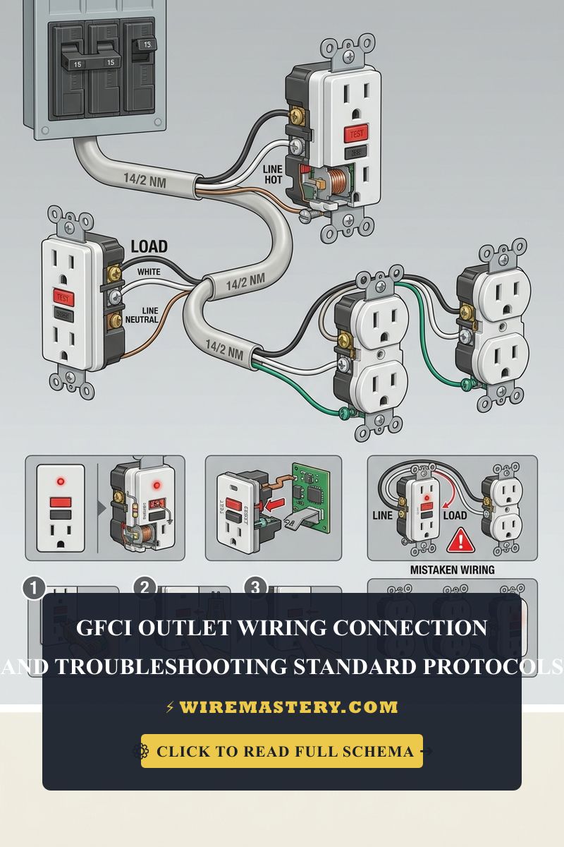
- The LINE vs. LOAD Terminal Boundary: The most frequent installation failure occurs when an installer treats the rear screws identically. The LINE terminals must accept exclusively the incoming 120V AC source conductors originating from the breaker panel center. The LOAD terminals (which ship factory-sealed beneath a yellow warning adhesive tape block) are reserved strictly for supplying downstream, daisy-chained standard outlets that require secondary GFCI protection from this single node.
- The Downstream Neutral Cross-Talk: If an operator cross-connects a downstream neutral wire originating from a completely separate branch circuit onto the GFCI Load silver port, the toroidal core will experience a continuous current deflection under load. This vector mismatch causes the device to trip instantaneously upon arming, preventing the mechanical reset latch from engaging.
- The Smart Auto-Status Requirement: Under modern safety testing frameworks (UL 943 standards), GFCI receptacles must incorporate an autonomous, continuous self-testing algorithm that periodically executes internal micro-fault simulations. If the internal logic board senses a breakdown in its sensing coil or sensing triac components, it must lock out power delivery permanently and display a solid red diagnostic LED warning marker.
Technical Materials & High-Sensitivity Differential Testing Toolkit
Safely opening high-moisture junction cavities and auditing low-level milliampere leakage lines requires specific diagnostic instruments and insulated hand tools:
| Electrical Auditing Tool | Primary Engineering Purpose & Safety Threshold |
|---|---|
| True RMS CAT III Multimeter | Category CAT III 600V certified to accurately map incoming hot phases from un-indexed links. |
| Three-Wire GFCI Loop Tester | Pocket tester equipped with a dedicated test button to inject a calibrated 5 mA leakage track. |
| 1000V Insulated Drivers Set | Square-drive (Robertson) tips to tighten terminal plates firmly without damaging screws. |
| Ratcheting Wire Strippers | Calibrated to cleanly remove exactly 3/4 inch of outer insulation off solid copper cores. |
| Class 00 Dielectric Gloves | High-density rubber insulation rated to isolate hands from up to 500V AC continuous. |
Conductor Diameters & Box Fill Capacities (NEC Table 314.16(B))
Because GFCI yokes house bulky solid-state sensing transformers, circuit boards, and trip mechanisms, their physical displacement volume is nearly triple that of a standard duplex outlet. Installers must prioritize NEC Article 314.16 cubic-inch clearances to prevent dangerous wire compression hotspots:
- 14 AWG Conductor Core (15-Amp Circuit Limit): White PVC jacket profile. Standard residential lighting and low-density outlet branches. Every #14 solid wire landing inside the enclosure box demands 2.00 cubic inches of free volume space.
- 12 AWG Conductor Core (20-Amp Circuit Limit): Yellow PVC jacket profile. Mandatory across high-moisture NEC Article 210.8(A) residential nodes including kitchen countertops, wet bars, bath centers, and outdoor runs. Every #12 wire demands 2.25 cubic inches of free volume space, while the bulky GFCI yoke itself mandates a double conductor volume deduction based on the supplying wire size.
Step-by-Step Field Blueprint: Multi-Point Downstream GFCI Integration
To configure a professional, code-compliant safety node that extends full ground-fault protection to multiple standard duplex receptacles down the line, apply this systematic field installation sequence:
1. Pre-Installation Energy Isolation Protocol
Locate your property’s primary distribution breaker subpanel. Identify and disengage the circuit breaker toggle feeding the target room zone. Back out the decorative faceplate screws. Prior to uncoupling any wire nuts or terminal plates, press your non-contact AC voltage tester deep into the box slots to confirm an absolute 0V AC state.
2. Identifying and Separating the Conductor Loops
A junction box containing a daisy-chained circuit will house four current-carrying wires (two Black hots and dos White neutrals) plus bare grounds.
- Separate all wire ends so they float isolated in mid-air. Restore breaker power temporarily.
- Probe the wires with your multitester to find the single pair that reads 120V AC. This is your LINE pair (incoming panel feed). Mark them with electrical tape.
- The remaining dead pair is your LOAD pair (traveling down to downstream rooms). Turn the subpanel breaker back to the full “OFF” position and lock it out before wrapping copper.
3. Terminating the GFCI Terminal Blocks
- Form clean, straight 1/2-inch shanks on the wire tips using your precision strippers. Insert the incoming LINE Black Hot wire directly beneath the pressure plate of the brass screw stamped LINE. Insert the incoming LINE White Neutral wire directly beneath the silver screw plate stamped LINE.
- Peel off the yellow protective warning adhesive tape covering the rear ports. Insert the outgoing LOAD Black Hot wire directly beneath the lower brass screw stamped LOAD. Insert the outgoing LOAD White Neutral wire directly beneath the lower silver screw stamped LOAD.
- Connect all bare copper safety ground conductors together using a twist-on wire nut, and route a dedicated ground pigtail directly to the green grounding hex screw on the GFCI yoke strap. Torque all side screws to exact manufacturer inch-pound specs to prevent progressive resistance faults. Pack the accordion-folded wires flat, mount the device flush, and restore system power.
🛠️ Weather-Resistant Weatherproof Stamp Note: Look closely at the mechanical face markings displayed across our outdoor distribution portfolios. Under the mandates of NEC 406.9, if you are replacing a faulty outlet located on an outdoor patio deck, garage enclosure, or damp crawlspace cavity, you are legally required to purchase a hardware module stamped with an explicit “WR” (Weather-Resistant) icon on the receptacle faceplate. WR devices incorporate high-impact UV-stabilized polycarbonate chassis molds and internal nickel-plated corrosion-resistant terminal assemblies to survive progressive humidity cycles without lockouts.
Troubleshooting Common Ground-Fault Breaker Trips
- The GFCI Receptacle Trips the Instant the RESET Button is Pressed: This symptom indicates an active Downstream Ground Fault or an internal Reverse Line/Load wiring error. If you accidentally cross-connected the incoming panel line wires into the lower LOAD ports, the internal microprocessor diagnostic chips will automatically freeze the mechanical latch open. Swap the runs back to the upper LINE ports. If wiring is correct, disconnect the wires from the LOAD side entirely; if the device now resets perfectly, the short circuit is buried inside the walls of the downstream room, requiring a sequential box insulation checkup.
- The Device Registers Power but the Downstream Outlets are Dead: Check the status of your internal connections. This fault confirms you have either connected downstream wires to the LINE side screws in parallel (which leaves them un-protected and dead during a trip) or the internal solid-state sensing board has suffered an inductive lightning surge blowout, destroying the line-to-load bridge contacts. Replace the GFCI module immediately.
- Upstream sensitive AFCI Breakers Trip Intermittently Upon Test Cycles: This occurs due to shared neutral return lines downstream. If the white neutral wire exiting the GFCI LOAD terminal block is tied or wire-nutted to a neutral line from an adjacent branch circuit inside a hidden junction box down the track, the return currents will split unevenly. The current transformer toroidal core detects a vector imbalance exceeding 6 mA, dropping the branch offline. Isolate the neutrals completely to clear the tracking noise.
National Electrical Code Safety & Placement Boundaries
Adhering to strict national installation codes protects your home investment, maintains property valuation, and ensures full property insurance compliance. The National Electrical Code strictly regulates life-safety ground-fault circuit interrupters under NEC Article 210.8 (Ground-Fault Circuit-Interrupter Protection for Personnel). Apply those GFCI provisions to the GFCI Outlet Wiring: Connection & Troubleshooting Standards covered here.
- Countertop Placement Boundaries (NEC 210.8(A)(6)): All 125V through 250V single-phase receptacles installed within kitchen environments to serve countertop surfaces must feature approved Class A GFCI protection. Furthermore, any general-use receptacle located within a strict physical radius of 6 feet (72 inches) from the outside top edge of any sink basin rim, wet bar, or laundry tub must incorporate GFCI safety protection, mitigating intense shock paths across high-moisture grids.
- Tamper-Resistant Mandates (NEC 406.12): All newly installed residential GFCI receptacles must be explicitly certified as Tamper-Resistant (TR), incorporating internal plastic spring shutters behind the slot faces to prevent child puncture accidents.
For the NFPA 70 provisions relevant to this guide on GFCI Outlet Wiring: Connection & Troubleshooting Standards, consult the Official NFPA 70: National Electrical Code (NEC).
Conclusion
Troubleshooting a GFCI receptacle starts with identifying the LINE and LOAD conductors, checking downstream neutral separation, and confirming that the box has adequate volume. After restoring power, use the device TEST and RESET controls to confirm operation and investigate nuisance trips without bypassing the protection. De-energize and verify the circuit before moving terminal wires; seek qualified help when a fault persists.







