Honeywell Thermostat Troubleshooting: Blank Screen & Heating Issues
Encountering a completely blank digital interface display window or dealing with sudden furnace ignition failures on a residential Honeywell thermostat is a highly stressful event for any homeowner, especially during extreme seasonal temperature dropouts. While these digital climate control hubs are engineered for high operational durability, they remain entirely dependent on a delicate, low-voltage control network loop. A blank screen does not automatically mean the thermostat processor hardware is permanently dead; instead, it is usually a clear symptom that an upstream electro-mechanical safety interlock or a thermal fuse circuit breaker has actively tripped to protect your property from a fire hazard.
This technical manual outlines a systematic structural troubleshooting process to isolate 24V AC power dropouts, trace hidden HVAC interlock faults, and resolve heating cycle failures safely.
Core Emergency Diagnostic Parameters
Before unmounting your control faceplate or handling any internal low-voltage conductors, memorize these core circuit benchmarks:
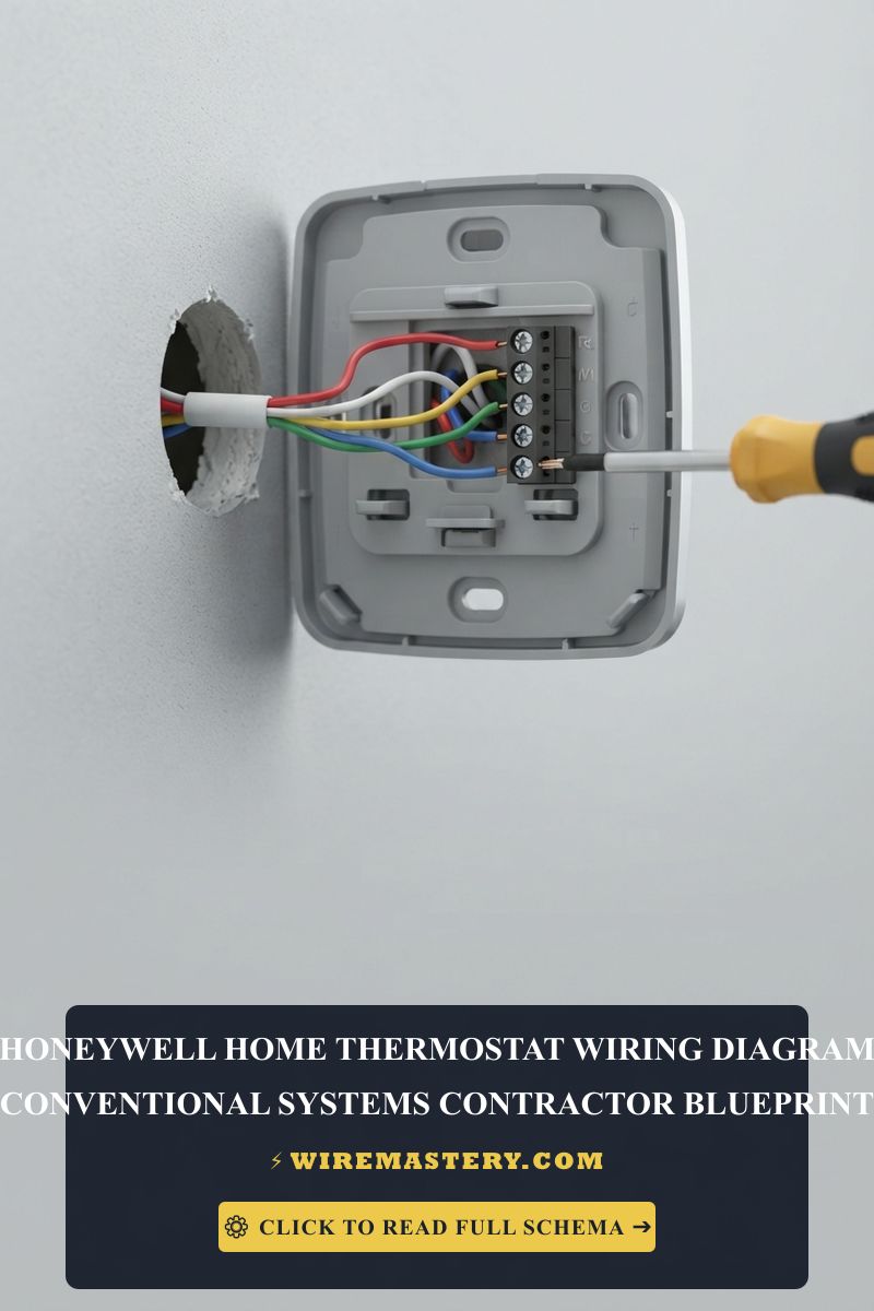
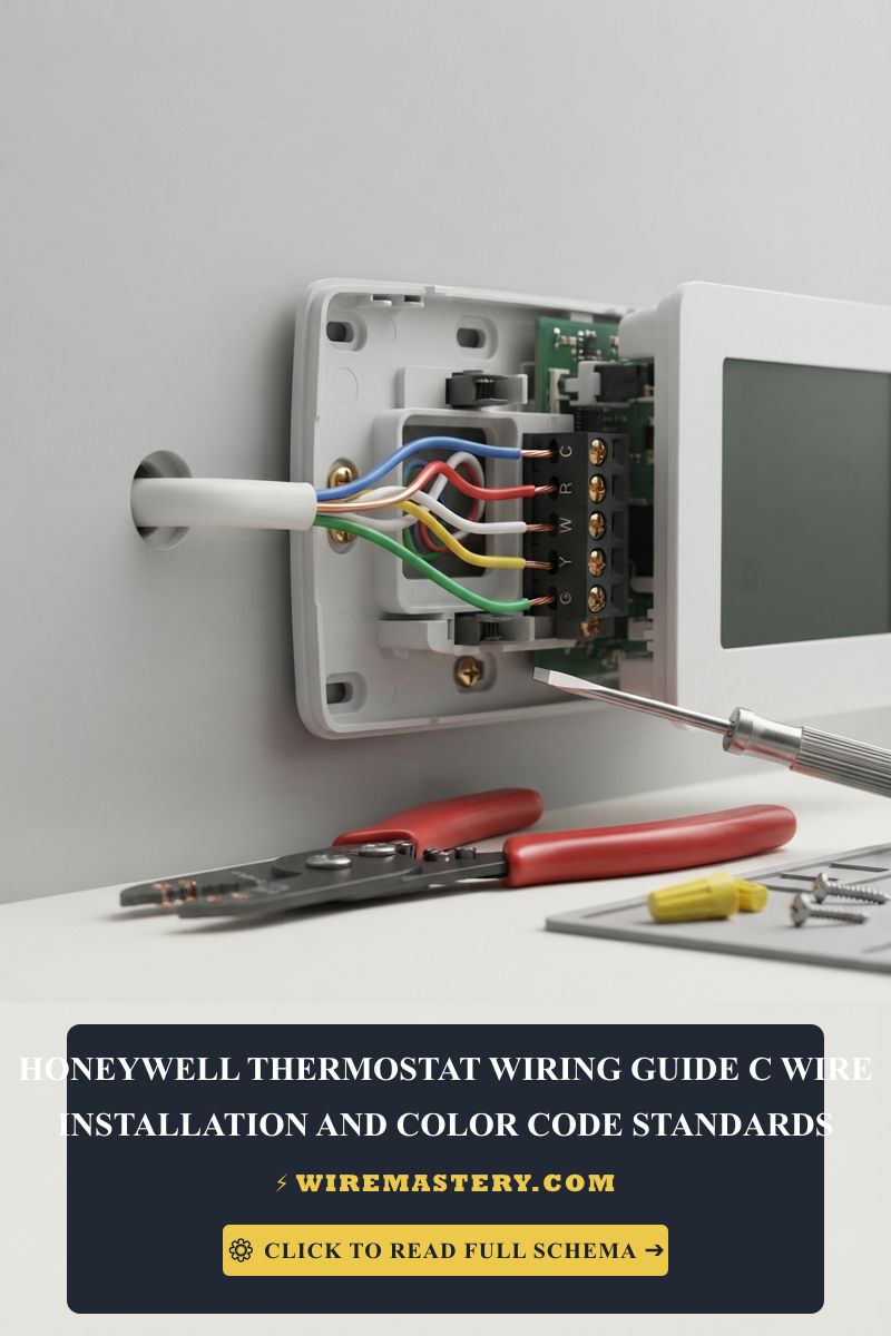
- The 24V AC Supply Line Requirement: Digital Honeywell thermostats require a continuous supply voltage of 24V AC (Alternating Current) flowing across the Red (R) and Common (C) terminal nodes to power the touchscreen, backlight, and Wi-Fi radios.
- The Power Source Point: The low-voltage power does not originate inside the wall cavity; it is generated by a step-down multi-tap transformer (converting 120V main utility line current down to 24V AC) located directly inside your basement furnace cabinet or attic air handler unit.
- The Safety Interlock Factor: Modern HVAC systems feature independent, series-wired safety switches designed to instantly cut all 24V control power the millisecond an unsafe operational state—such as a clogged drain line or an unlatched cabinet panel door—occurs.
Technical Materials & Diagnostic Testing Toolkit Checklist
Safely auditing and measuring low-voltage HVAC control loops requires specific trade testing instruments and precision hand tools:
| HVAC Trade Tool / Material | Primary Engineering Purpose |
|---|---|
| Digital Auto-Ranging Multimeter | Measures exact AC voltage parameters (0V to 30V) across terminal shanks to trace power drops. |
| Precision Needle-Nose Pliers | Used to straighten solid copper conductor leads and safely pull low-voltage blade fuses. |
| Non-Contact AC Voltage Tester | Audibly confirms complete 120V line-voltage isolation inside the furnace chassis enclosure. |
| Replacement 3-Amp Automotive Fuses | Standard violet blade fuses mandatory to repair short-circuited furnace control boards. |
| Electrical Contact Cleaner Spray | Fast-evaporating solvent used to clean carbon scaling and oxide crusts off dirty terminal pins. |
Sizing Conductor Gauges & Ampacity Constraints
To prevent signal attenuation, parasitic resistance, and erratic temperature readings across long structural runs between the living space and the basement utility enclosure, you must ensure your system utilizes the correct wiring diameter matching national safety frameworks:
- 18 AWG Solid Copper (The Low-Voltage Code Standard): Standard thermostat wiring cable bundles (such as 18/5 or 18/7 sheaths) utilize solid copper cores. This thickness provides the exact cross-section area required to carry continuous 24V AC pilot signal currents without overheating or inducing voltage drops.
- Insulation Integrity Requirements: The outer colored insulation PVC layers must be completely free of micro-nicks or horizontal scores. If an amateur installer scratches the nylon coating while stripping wires, the exposed copper will touch adjacent terminal pins, triggering an immediate short circuit.
The Diagnostics Phase: Tracing the 3 Hidden “Blank Screen” Triggers
When a Honeywell thermostat screen goes completely pitch-black, 90% of homeowners replace the unit unnecessarily, unaware that the true fault lies inside an upstream HVAC component. Before discarding hardware, execute this structured trade diagnostic sequence to locate the hidden culprit:
1. The Furnace Safety Door Interlock Switch Fault
Inside almost every North American residential forced-air gas or electric furnace cabinet, manufacturers install a spring-loaded safety plunge button behind the main service access panel door.
- The Mechanism: This switch acts as a dead-man safety interlock. When the furnace door is closed tightly, the panel panel compresses the muelle button, allowing 120V main power to flow to the transformer control board.
- The Failure Point: If a homeowner opens the door to inspect the air filter and fails to secure the cabinet door latches completely when finished, the switch will pop out, cutting all 120V main line power to the transformer. This instantly kills the 24V supply to the wall, causing the Honeywell screen to drop completely blank.
2. The Condensate Float Switch Emergency Lockout
Central air conditioning and modern high-efficiency condensing gas furnaces generate high volumes of water runoff during operation. This water passes through an indoor PVC drain pipe line out to a floor drain pump enclosure block.
- The Mechanism: Inside the main PVC drain line path, technicians install an inline safety overflow device known as a condensate float switch.
- The Failure Point: If the PVC drain line becomes clogged with biological sludge, algae, or dust mounds, the condensation water back-floods the pipe layout. The internal plastic float ring rises to the top of its chamber, mechanically breaking the continuous 24V AC Red (R) wire current loop. This emergency lockout cuts all control power to the wall instantly to kill the cooling loop before an expensive basement floor flood occurs.
3. The Blown 3-Amp Blade Fuse on the Control Board
If you accidentally touched the raw copper tip of the Red power wire to the Blue Common wire or the chassis steel while replacing your thermostat base plate, you triggered a dead short circuit.
- The Mechanism: To prevent a low-voltage short circuit from destroying the expensive primary microprocessor circuit board inside your furnace, engineers mount a standard automotive-style blade fuse (typically a purple 3-Amp fuse or an orange 5-Amp fuse) directly onto the terminal strip face.
- The Failure Point: The subsecond short circuit instantly snaps the thin internal metal filament of this blade fuse. The circuit drops offline completely, shutting down all 24V communication lines to the living spaces.
Step-by-Step Honeywell Control Board & Safety Circuit Repair
Once your diagnostics phase narrows down the root cause of the power dropout or thermal lockout, follow this systematic field protocol to execute the physical repairs safely:
1. Main Infrastructure Energy Isolation
Before opening any mechanical furnace housing panel doors, navigate to your property’s primary distribution breaker box. Locate the dedicated breaker switches labeled “Furnace,” “Heating,” or “Air Handler” and trip them to the full “OFF” position. Go to the utility closet and turn off the standalone toggle emergency switch (which often features a red cover plate face) mounted on the wall stud framing next to the unit cabinet.
2. Extracting and Replacing a Blown 3-Amp Control Board Fuse
If a low-voltage short circuit occurred during installation, use this sequence to replace the safety fuse link:
- Remove the upper access door panel of the furnace cabinet to expose the primary electronic circuit board module.
- Locate the small, colorful automotive blade fuse (typically a violet 3-Amp fuse or tan 5-Amp fuse) plugged directly into the center of the board trace lines.
- Grip the plastic top of the fuse firmly using your needle-nose pliers and pull it straight out of its socket clips.
- Hold the fuse body up to a bright flashlight beam. If the inner metal bridge filament is snapped, cracked, or if the transparent casing shows black carbon scoring, the fuse has sacrificial-blown.
- Push a brand-new, identical replacement 3-Amp blade fuse firmly into the empty socket ports. Never substitute a higher-amperage fuse or a copper bypass wire, as doing so will instantly destroy the entire $400 primary control board during the next short circuit event.
3. Clearing the Condensate Drain Lockout
If your float switch has broken the 24V loop due to a line blockage:
- Locate the plastic overflow switch puck assembly installed along the main white PVC furnace drain lines.
- Lift the electronic sensor switch top carefully out of its PVC housing well. If the well cavity is completely full of standing water, the line is fully blocked.
- Hook a specialized wet/dry shop vacuum to the exterior outdoor terminal exit point of the drain pipe line and suck out the biological sludge, mold crusts, and loose sediment blocks clogging the run.
- Once the water drains out completely and the internal plastic float ring drops back down to the baseline floor of its casing, the internal safety contact points will snap closed, instantly restoring the continuous 24V AC Red (R) wire loop back to the living spaces.
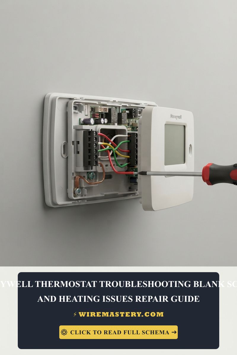
🛠️ Contractor Circuit Reality Check: Look closely at the realistic 24V AC relay mapping sequences and device assets displayed across your guide frameworks. Notice that digital climate systems require clean ground loops. When troubleshooting heating cycle failures using digital field instruments, always verify that your multimeter probes maintain firm contact with shiny, unpainted sheet metal surfaces or dedicated ground terminal lugs inside the cabinet frame to guarantee an accurate voltage measurement.
Diagnosing Heating Cycle Failures (Thermostat On, But No Heat)
If your Honeywell digital display panel powers up perfectly but your property’s furnace fails to ignite or blow hot air when you raise the target temperature setting, the fault lies down in the ignition control loops:
The 24V AC Pilot Signal Voltmeter Audit
To verify if your Honeywell thermostat is successfully communicating with your heating hardware, perform a live low-voltage output audit using your auto-ranging digital multimeter:
- Pop the Honeywell display faceplate forward off its wall mounting subbase, keeping all wires connected to their terminal slots.
- Set your multimeter dial to AC Voltage mode (V AC).
- Place your black multi-tester probe onto the C (Common) terminal screw shank and place your red probe onto the W (Heat) terminal screw shank.
- Enter your Honeywell software menu and set the operational state to HEAT mode, raising the setpoint temperature at least 5 degrees above the active room reading.
- Analyze the Digital Multimeter Readout:
- If the meter reads 0V AC: The thermostat’s internal digital relay chip has failed or is unconfigured. The software is not sending the call for heat down the line.
- If the meter reads 24V AC: The thermostat is functioning perfectly and successfully sending power down the white wire line. The heating failure is caused by an unlit gas pilot light, a fouled furnace flame sensor rod, or a dead ignition control module inside the furnace chassis.
Managing Compatibility Layout Restrictions
Before executing extensive wiring modifications, ensure your hardware architecture is fully compatible with your property’s core equipment. Honeywell Home devices are explicitly listed for specific HVAC categories:
- Conventional Gas/Electric Systems: Demand independent 24V AC outputs across the standard R, C, W, Y, and G terminal matrix.
- Millivolt Systems (Wall Heaters / Fireplaces): Legacy wall heaters utilize self-powered thermopiles that output a microscopic 750 millivolts DC. Attaching a standard 24V Honeywell smart thermostat to a millivolt fireplace loop without an isolating transformer interface relay will instantly destroy the low-voltage gas valve components.
National Electrical Code Compliance for HVAC Circuits
Adhering to strict electrical installation codes shields your home investment, maintains property valuation, and ensures full insurance compliance. The National Electrical Code strictly regulates general low-voltage automation lines and HVAC safeties under NEC Article 725 (Remote-Control, Signaling, and Power-Limited Circuits):
- Class 2 Short-Circuit Boundary Protections: Thermostat wire lines operate as low-voltage Class 2 signal circuits. The NEC mandates that these lines must be protected by an overcurrent device (such as the 3-Amp board blade fuse) to restrict active power thresholds in the event of an insulation breakdown, minimizing fire induction risks inside finished walls.
- Separation of Circuits (NEC 725.136): All Class 2 low-voltage thermostat conductors must maintain a minimum 2-inch clear physical separation from any high-voltage 120V/240V main branch power lines inside electrical enclosures and wall cavities unless enclosed in approved conduits, preventing high-voltage arcing from crossing into digital home grids.
For the NFPA 70 provisions relevant to this guide on Honeywell Thermostat Troubleshooting: Blank Screen & Heating Issues, consult the Official NFPA 70: National Electrical Code (NEC).
Conclusion
This article explains Honeywell thermostat troubleshooting parameters and executing low-voltage safety circuit repairs transforms complex climate faults into clean, systematic solutions. By resolving furnace door interlock panel gaps, cleaning out blocked PVC condensation drain lines, and verifying 24V AC call signals across W and C terminals with an auto-ranging multimeter, you achieve a professional, home environment. For final checks, complete electrical power isolation testing, utilize certified diagnostic instruments, and execute every terminal step with code-compliant precision.