Honeywell Thermostat Wiring Guide: C-Wire & Color Code Standards
Installing a Honeywell thermostat is one of the most effective DIY projects to enhance your home’s HVAC efficiency. However, working with low-voltage control lines requires precision. Connecting the continuous 24V power loop via the common wire (C-wire) is crucial for keeping digital touchscreens and Wi-Fi modules online without draining backup batteries.
Exact Honeywell thermostat wiring color codes, terminal connections, and tools required to achieve full compliance with the National Electrical Code (NEC).
Understanding the C-Wire Power Loop
The C-wire (Common wire) completes the low-voltage electrical circuit back to your furnace or air handler’s 24V transformer. Unlike traditional mechanical thermostats that simply open and close basic mercury switches, modern smart thermostat hardware demands constant power handling.
- Continuous Power Distribution: Eliminates system power-stealing issues and frequent battery replacements.
- System Reliability: Prevents short-cycling behavior on modern heat pumps and multi-stage furnaces.
- Smart Automation Support: Supplies steady current required for continuous background Wi-Fi syncing.
Honeywell Thermostat Wiring Colors & Terminal Standards
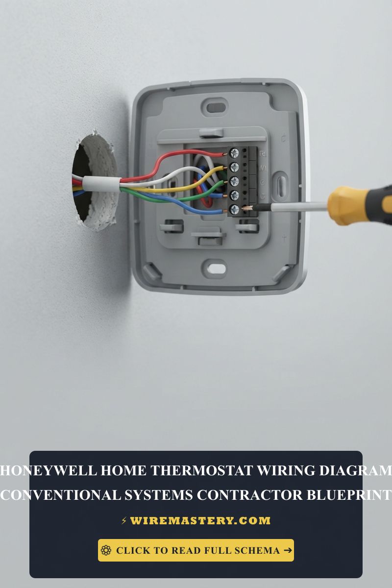
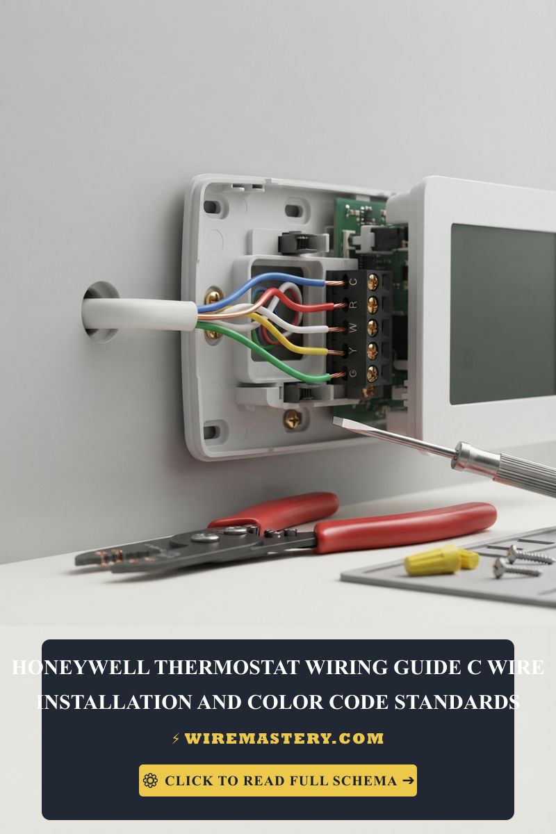
To prevent short circuits on your HVAC control board, you must map your solid copper wires to the correct letters on the terminal subbase. Note that standard residential HVAC installations in the United States follow specific industry color conventions, although terminal designations take legal precedence over wire insulation colors.
Standard Thermostat Terminal Designations
| Terminal Letter | Standard Wire Color | Technical Function |
|---|---|---|
| C | Blue / Black | Common: Completes the 24V circuit to supply continuous power. |
| R / RC / RH | Red | Power: 24V transformer feed (RC for cooling, RH for heating). |
| W / W1 | White | Heat Stage 1: Signals the gas furnace or electric strips to fire up. |
| Y / Y1 | Yellow | Cooling Stage 1: Controls the outdoor compressor contactor loop. |
| G | Green | Indoor Blower Fan: Manages the indoor air circulation blower. |
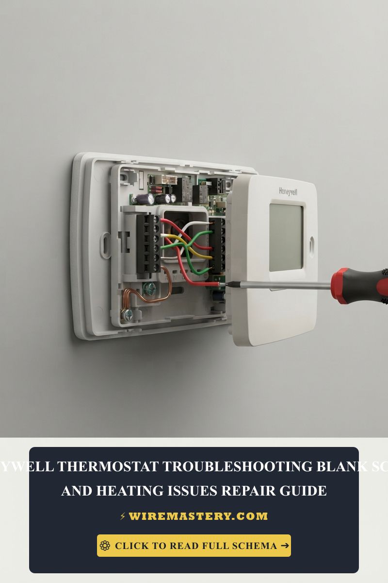
🛠️ Wiring Reality Check: Always verify terminal letters rather than relying blindly on insulation colors. As shown in advanced industrial testing mockups, custom multi-conductor thermostat cables (like 18/5 or 18/7 wire bundles) may utilize varied coloring patterns depending on the previous technician’s installation choices. Always label your lines before removing an old baseplate.
Advanced Multi-Stage & Heat Pump Wires
- O / B: Reversing valve control lines for residential heat pump changeover modes.
- E / AUX: Emergency or auxiliary heat activation during extreme sub-zero weather dropouts.
Step-by-Step C-Wire Installation and Configuration
1. Essential Tools & Safety Preparation
Before handling low-voltage climate lines, gather your insulated hand tools: a digital multimeter or voltage tester, wire strippers, small precision screwdrivers, and an alignment level.
CRITICAL SAFETY STEP: Switch off the dedicated circuit breaker powering your indoor furnace or air handler unit. Never rely solely on turning off the thermostat interface. Verify the line is completely de-energized using your multimeter across the R and C terminals before exposing the raw copper conductors.
2. Sourcing and Running an 18 AWG Line
Modern thermostat communication relies strictly on 18 AWG solid copper conductors. If your existing wall bundle lacks a dedicated wire for the C terminal:
- Examine the Wall Cavity: Gently pull the wire sheath out of the drywall. Often, an unused blue or black wire is tucked away by the original installer.
- Install a C-Wire Power Adapter: If running a brand new 18/5 solid conductor line from the basement or attic is impractical, integrate an external C-wire transformer kit directly into the furnace control terminal strip.
3. Securing Connections to the Subbase
Strip exactly 1/4 inch of insulation from each solid conductor using your wire strippers. Insert the bare copper wire firmly into the corresponding terminal push-pad or screw clamp (R to R, C to C, W to W, Y to Y, G to G). Ensure no bare copper strands overlap adjacent terminals, as this creates an immediate short circuit risk that can destroy your HVAC system’s 3-amp blade fuse.
Troubleshooting Common Configuration Faults
- Thermostat Display Remains Blank: Verify the HVAC door safety switch is fully engaged. Next, check the 24V transformer output or look for a blown fuse on the integrated furnace control board.
- System Blows Cool Air During Heating Cycles: This indicates a terminal mismatch between your W (heating) and Y (cooling) control lines, or an unconfigured heat pump reversing valve setting within the Honeywell system setup menu.
- Intermittent Wi-Fi Dropouts: Confirm steady 24V AC power distribution across the C and R terminals using your digital multimeter. Low voltage dropouts can cause smart chips to reboot under heavy system loads.
NEC Compliance & Official Safety Standards
Adhering to official structural codes ensures your low-voltage installations are completely safe and code-compliant. The National Electrical Code strictly regulates Class 2 circuit power limitations, wire insulation thresholds, and separation rules from high-voltage branch power circuits to avoid electrical arcing or fire induction hazards inside residential walls.
For current NFPA 70 guidance on low-voltage HVAC controls, C-wire connections, terminal identification, and separation from line-voltage wiring, consult the Official NFPA 70: National Electrical Code (NEC). Apply those provisions to the Honeywell Thermostat Wiring Guide: C-Wire & Color Code Standards scenario covered in this guide.
Conclusion
This guide covers executing a Honeywell thermostat installation using a continuous 24V C-wire loop stabilizes your smart home ecosystem and ensures seamless heating and cooling performance. By decoding standard terminal colors, tracking your 18 AWG solid copper connections, and respecting NEC guidelines, you protect your property infrastructure while enjoying optimized energy efficiency throughout the year.