How Many Outlets on a 20-Amp Circuit? NEC Sizing Guide
Determining the maximum number of electrical receptacles allowed on a dedicated 20-amp branch power line is a foundational step when drafting residential blueprints or executing utility panel additions. While amateur installers frequently assume there is a single universal limit, the National Electrical Code (NEC) addresses branch circuit layout through two completely independent pathways depending on whether the building is classified as a residential dwelling or a commercial infrastructure. Miscalculating these continuous vs. non-continuous thresholds results in progressive thermal breaker tripping and severe code enforcement violations.
This manual demystifies the 120V electrical load calculations, the mandatory 180VA yoke allocation equations, and strict physical separation limits matching the latest National Electrical Code (NEC) standards.
Core Circuit Load Parameters
Before routing branch conductors to a sequence of outlet enclosures, verify these core engineering thresholds:
- The 80% Continuous Load Rule: Under NEC Article 210.20, any electrical load expected to remain active continuously for 3 hours or more (such as heavy commercial lighting or space heaters) must not exceed 80% of the maximum circuit rating. For a standard 20A branch, this restricts continuous draw to exactly 16 Amps.
- Total Volt-Ampere (VA) Capacity: The complete power capacity available on a standard single-phase 120V 20-amp circuit is calculated using the standard wattage formula (20 Amps × 120 Volts = 2,400 VA).
- Conductor Gauge Constraints: Sizing requirements are absolute; wiring a 20-amp overcurrent protection breaker with anything less than a heavy solid copper core violates federal safety codes.
Technical Materials & Rough-In Enclosure Checklist
Safely executing receptacle string routing and panel terminations requires specific trade equipment and calibrated testing instruments:
| Electrical Trade Tool | Primary Technical Purpose |
|---|---|
| Digital Auto-Ranging Multimeter | Measures exact AC line voltages and tests circuit path continuity across long loops. |
| Non-Contact Voltage Detector | Audibly verifies full circuit isolation inside junction box enclosures before trade work. |
| Automatic Wire Strippers | Calibrated to shear outer insulation jackets clean off #12 AWG solid copper cores. |
| GFCI Receptacle Circuit Tester | Plugs directly into sockets to instantly diagnose reversed polarity or open neutral faults. |
| Calibrated Torque Driver | Tightens side terminal screws to the manufacturer’s exact listed inch-pound parameters. |
Sizing Conductor Gauges & Amperage Capacities
Selecting an incorrect wire diameter introduces massive internal resistance, leading to heat accumulation behind finished walls long before the circuit breaker can safely disengage. The NEC strictly regulates overcurrent thresholds based on the conductor’s physical cross-section profile under NEC Article 310.16:
- 12 AWG Solid Copper (Mandatory Standard): This is the required wire gauge size for all 20-amp residential branches. Standard Romex bundles are wrapped in a distinct Yellow PVC sheath outer jacket for fast field inspection identification.
- 14 AWG Solid Copper (Strictly Prohibited): Enclosed inside white jackets, 14 AWG is rated exclusively for 15-Amp lines. Connecting a 14 AWG conductor line anywhere along a 20-amp circuit is a catastrophic code violation that triggers direct fire hazards.
Resolving the Sizing Question: Residential Dwelling vs. Commercial Rules
To calculate exactly how many receptacles can hook into your line, you must isolate your building development context:
1. The Commercial Framework: The 180 VA Rule (NEC 220.14(I))
In commercial offices, industrial workshops, and multi-tenant retail infrastructures, the NEC treats outlets with strict mathematical limits. The code mandates that each individual single or duplex receptacle strap yoke must be calculated as a fixed apparent load of 180 VA regardless of what is plugged into it.
To determine the absolute maximum allowable code limit, you divide the total circuit capacity by the yoke allocation index:
Maximum Commercial Outlets = Total Circuit Volt-Amps / Per-Yoke Code Burden = 2,400 VA / 180 VA = 13.33
Therefore, under commercial enforcement guidelines, you are legally restricted to a maximum of 13 outlets on a single 20-amp circuit loop.
2. The Residential Framework: The Demand Diversity Rule
For standard family homes, apartment units, and living common spaces, the NEC does not enforce a fixed numerical limit on the number of outlets per circuit. The code recognizes that residential outlets experience high diversity; a homeowner might plug a 1,500W hair dryer into one slot while the other nine outlets remain empty.
Instead, residential layouts are calculated based on the home’s total square footage floor area, allocating 3 Volt-Amps per square foot under NEC Article 210.11(A). However, while you can technically run 15 to 20 general receptacles on a single line in a residential layout, standard contractor best-practices dictate limiting residential strings to 10 or 12 outlets per circuit to maintain a comfortable headroom safety buffer.
Special Residential Exceptions: Dedicated 20A Kitchen & Bathroom Circuits
While general living areas allow high outlet diversity, the National Electrical Code enforces strict boundaries when dealing with high-draw residential utility zones. You cannot mix general bedroom lighting loops with infrastructure nodes under federal safety codes.
Small Appliance Branch Circuits (SABC - NEC 210.52(B))
The NEC mandates that a residential kitchen counter space must be supplied by a minimum of two independent 20-amp Small Appliance Branch Circuits.
- The Isolation Rule: These specific 20A circuits must feed exclusively kitchen countertop receptacles, refrigeration nodes, and dining room plugs.
- Lighting Prohibitions: You are strictly prohibited from connecting ceiling light fixtures, exhaust fans, or under-cabinet task lighting to these lines. This layout isolation ensures that if a high-wattage toaster oven trips the 20A breaker, the room is not instantly plunged into complete pitch-black darkness.
Laundry and Bathroom Nodes (NEC 210.11(C))
Similar to kitchen layouts, the code requires a dedicated 20-amp circuit feeding the bathroom receptacles and a separate dedicated 20-amp loop for the laundry room plug array. These lines cannot travel outside their respective structural zones to supply outlets in adjacent family rooms.
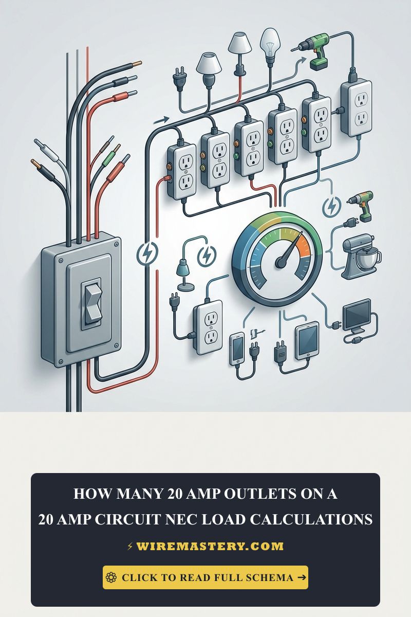
🛠️ Receptacle Chain Configuration Note: Look closely at the production mockup layouts displayed across your technical manuals. Notice how downstream outlets are interconnected using two distinct installation options: daisy-chaining directly through the terminal screws or utilizing balanced copper wire pigtails inside the box cavity. In high-density appliance environments, utilizing the pigtail method ensures that if one receptacle face burns out or suffers a physical breakdown, the downstream path stays fully operational without breaking neutral continuity.
Step-by-Step Receptacle Loop Load Sizing Manual
1. Conducting the Connected Appliance Wattage Audit
Before layout planning your receptacle positions, sum the maximum active power demands of the hardware you intend to deploy simultaneously. To convert equipment Wattage labels into active Amperage current draw values, apply the standard Ohm’s Law formula:
Amps = Watts / Voltage
If a user intends to connect a heavy commercial space heater drawing 1,500 Watts and a high-performance desktop computer drawing 400 Watts to the same 120V line branch:
Total Amperage Burden = (1500 + 400) / 120 = 15.83 Amps
Since 15.83 Amps sits directly at the absolute limit of the 16-Amp continuous load threshold for a 20A breaker, this single pair of devices will consume 99% of the safe capacity. Running any secondary appliance (like a laser printer or vacuum) on the remaining outlets along that string will instantly trigger a thermal trip at the panel.
2. Splicing Multi-Outlet Receptacle Chains
- Route your Yellow 12/2 NM-B Romex cable lines into your electrical box enclosures, maintaining strict box fill volume compliance parameters.
- Strip exactly 3/4 inch of insulation off your conductor ends. Form uniform clockwise loops using your needle-nose pliers.
- Connect the incoming Black hot wires to the brass terminal screws (labeled HOT) and the incoming White neutral wires to the silver terminal screws (labeled WHITE/NEUTRAL).
- Secure your bare copper equipment safety grounds directly to the green hex grounding screws, bonding the circuit firmly to the rear metallic or plastic box framework.
Troubleshooting Common Receptacle Overload Failures
- The Breaker Trips Frequently in the Kitchen: This is almost always a symptom of exceeding your SABC load capacity boundaries. If a homeowner plugs a 1,200W coffee maker and a 1,500W toaster into two different slots on the same kitchen counter circuit, the combined draw reaches 22.5 Amps, instantly triggering a thermal overcurrent trip. The solution requires redistributing your appliances across both independent 20A kitchen circuits.
- The Receptacle Body Feels Warm to the Touch: An immediate red flag for dangerous localized high resistance. This dropout is typically caused by poor terminal screw torque or utilization of loose rear backstabbed holes instead of side-wire terminations. Turn off the breaker immediately, pull the device, and torque the screws tightly to eliminate micro-arcing.
- Lights Blink on Alternate Circuits When Outlets Engage: Indicates a high voltage drop over long distance runs. If your 12 AWG circuit extension exceeds 100 feet, the internal conductor resistance will choke the current loop, causing voltage sags. You must upsize the structural run to #10 AWG wire to stabilize the line voltage drop below the legal 3% target.
NEC Compliance & Branch Sizing Integrity
Adhering to strict construction regulations protects your property value, ensures full insurance compliance, and shields your family against hidden arching faults behind drywall. The National Electrical Code strictly regulates general-use receptacles, load factors, and safety interlocks under NEC Article 210 (Branch Circuits), Article 220 (Branch-Circuit Calculations), and the thermal constraints of Article 314:
- Tamper-Resistant Mandates (NEC 406.12): All newly installed or replaced residential 20-amp receptacles must be explicitly certified as Tamper-Resistant (TR), incorporating internal plastic safety shutters to prevent foreign objects from bridging live terminal paths.
- GFCI/AFCI Protections: Receptacles installed in wet or accessible environments must feature integrated Ground-Fault (GFCI) protection, while living area branches demand Arc-Fault (AFCI) breakers to suppress tiny spark tracks before fire induction occurs.
For the NFPA 70 provisions relevant to this guide on How Many Outlets on a 20-Amp Circuit? NEC Sizing Guide, consult the Official NFPA 70: National Electrical Code (NEC).
Conclusion
This guide covers executing residential load calculations and layout planning how many outlets can go on a 20-amp circuit upgrades your property’s infrastructure durability and ensures full alignment with modern safety codes. By applying the mandatory 180VA commercial calculation formula where required, limiting residential receptacle strings to a comfortable 10-outlet safety headroom buffer, and isolating your SABC kitchen lines from lighting grids, you build an expert, electrical network. For final checks, complete panel breaker power isolation testing, utilize certified field instruments, and execute every terminal step with safety-first precision.







