How to Change a Smoke Detector Battery: Hardwired Chirping Fix
Executing a reliable, code-compliant residential smoke detector battery replacement or deploying a systematic technical fix to eradicate an intermittent, localized hardware chirping sequence demands a disciplined understanding of dual-voltage life-safety networks, solid-state capacitive discharge profiles, and multi-station tandem signaling loops. Modern residential fire warning infrastructures operating under updated North American building regulations are not standalone, isolated battery pods; they utilize a sophisticated 120V AC hardwired power backbone equipped with a secondary DC battery backup supply. These units are interconnected in parallel via a dedicated third conductor signaling highway, ensuring that if a single optical chamber detects microscopic carbon particulates within a remote utility basement, an immediate cross-trigger signal launches to activate the sounder diaphragms across every upper floor boundary simultaneously.
This technical manual outlines the physical mechanics of tandem signaling loops, the thermodynamic chemistry of backup power cell choices, and advanced field methodologies to drain locked micro-processor logic gates.
Core Life-Safety Engineering Parameters
Before uncoupling factory quick-connect harness plugs or ascending staging steps to handle ceiling-mounted enclosures, decode these foundational parameters:
- The 9V DC Interconnect Signaling Matrix: Hardwired multi-station alarm arrays utilize a three-conductor wiring framework: 120V Line Hot (Black), Grounded Neutral (White), and the Tandem Interconnect Link (typically solid Red or Orange). When a local chamber initiates an alarm state, its internal solid-state triac relay gates an instantaneous 9V DC signaling pulse down the red conductor track, forcing all adjacent network processors to cycle into a matching alarm loop within milliseconds.
- The Capacitive Logic Lockout: The most frequent failure mode encountered during DIY maintenance is a smoke detector that continues to emit a sharp, single localized chirp precisely every 30 to 60 seconds even after a brand-new battery cell is locked inside the drawer. This occurs because the unit’s internal power supply capacitors retain a latent residual static charge, blinding the integrated sensor chip to the upgraded voltage profile.
- The 10-Year Electrochemical Limit: Under the strict mandates of NFPA 72 (National Fire Alarm and Signaling Code), the internal sensing chambers (both photoelectric and ionization profiles) undergo permanent chemical saturation and structural decay over time. Every device must be completely discarded and replaced exactly 10 years from its printed manufacturing stamp date, regardless of continuous line voltage availability.
Technical Materials & Fire-Safety Maintenance Toolkit Checklist
Safely isolating line-voltage subpanel feeds and cleaning microscopic particulate chambers requires specific testing instrumentation and non-conductive trade tools:
| Life-Safety Trade Tool | Primary Engineering Purpose & Safety Threshold |
|---|---|
| Digital True RMS Multimeter | Category CAT III 600V certified to audit 120V line inputs and measure 9V battery cell potentials. |
| Non-Contact AC Voltage Tester | Proximity sensor to audibly guarantee 100% harness de-energization before quick-plug handling. |
| Compressed Gas Duster Canister | Delivers an intense, moisture-free dry air blast to flush out optical sensing chamber dust nets. |
| Dielectric Contact Cleaner Solvent | Purges oxidized carbon scales and film residue off the low-voltage pin block interfaces. |
| Heavy-Duty ANSI-Rated Step Ladder | Industrial grade fiberglass step stool to access elevated ceiling junction box plates safely. |
Conductor Profiles & Tandem Raceway Boundaries (NEC Article 760)
Routing or extending hardwired fire safety signaling networks requires strict adherence to the conductor sizing frameworks and insulation parameters enforced under NEC Article 760 (Fire Alarm Systems):
- 14/3 AWG Solid Copper Conductor (15-Amp Circuit Limit): The standard multi-conductor sheathed assembly (NM-B Romex) deployed for residential alarm runs. The black core supplies constant ungrounded 120V AC utility power, the white completes the grounded neutral loop, and the red link operates exclusively as the 9V tandem data highway.
- Conduit Isolation Restrictions (NEC 760.136): Low-voltage class data signal tracks or automated low-voltage sensor runs are strictly prohibited from entering the same raceways, conduits, or junction boxes housing these 120V hardwired smoke detector branch lines unless isolated by an approved non-combustible metallic partition sheet.
Technical Phase 1: The Safe Hardwired Power Isolation and Battery Unpacking
To replace an exhausted backup power cell and resolve chronic low-battery chirping alerts without receiving dangerous electrical shocks from raw quick-plug harness terminals, apply this trade safety protocol:
1. Hard Panel Circuit Isolation
Navigate to your property’s primary service panel center. Locate the dedicated breaker toggle labeled “Smoke Detectors” or “Lighting Branch” and flip it to the absolute “OFF” position. Note: Modern building codes prohibit placing smoke alarms on an isolated single circuit; they are intentionally tied into a frequently used general lighting loop to prevent a homeowner from leaving the system de-energized unnoticed.
2. Physical Extraction and Voltage Verification
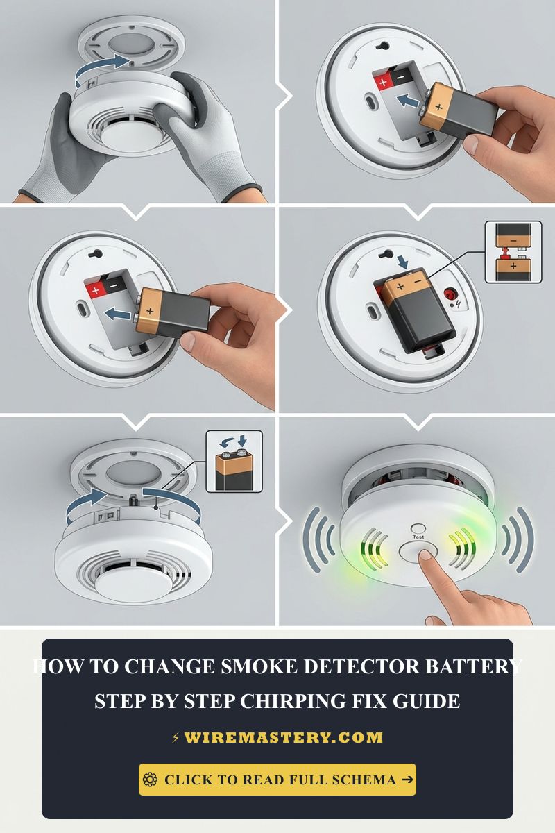
Ascend your fiberglass step ladder safely. Grip the outer plastic casing of the smoke detector body and rotate it counter-clockwise roughly 15° to disengage the chassis alignment tabs from the ceiling mounting ring plate. Lower the unit gently to expose the rear wire harness cavity. Prior to separating any plastic parts, press your non-contact AC voltage tester deep into the connector wire tracks to verify an absolute 0V AC state exists across the harness.
3. Quick-Plug Harness Separation
Squeeze the dual locking tabs on the sides of the three-pin factory wire harness connector plug and pull it straight out from the rear of the smoke alarm casing. This completely isolates the hardware device from the house grid wiring loop, allowing safe bench-top handling. Open the integrated battery hatch door and slide out the exhausted power cell.
Technical Phase 2: Capacitive Logic Draining & Optical Chamber Clearing
Once the exhausted backup power cell has been removed and the unit is fully un-plugged from the 120V AC wiring harness, a field technician must execute a complete memory clearing protocol to erase the latent static charge locked inside the system processors:
1. The 20-Second Micro-Processor Reset Protocol (Draining the Capacitors)
Failing to clear the internal solid-state capacitors forces the integrated chip to continuously loop the old low-voltage error registers, triggering persistent chirping even if you insert a fresh premium lithium cell.
- With the 120V wire harness plug fully disconnected and the old battery removed from the drawer.
- Press and hold down the primary physical “TEST” button located on the front face of the alarm casing continuously for 15 to 20 seconds.
- The System Response: You will hear a short, muted half-chirp or a faint terminal beep as the internal capacitor banks completely discharge their stored static current loop down to a true 0V state. This structural reset flushes the hardware memory banks clean, resetting the low-voltage diagnostic monitoring gate.
2. Pneumatic Saneing of the Internal Sensing Chamber
Ambient carbon dust mats, loose drywall dust from renovations, and microscopic spider webs inside the detector casing scatter light paths, causing intense false alarms or continuous error chirping.
- Take your canister of compressed gas duster. Insert the long precision straw attachment nozzle directly into the physical louvers or perimeter mesh screens surrounding the internal optical chamber.
- Deliver 4 to 5 intense, short blasts of completely dry air into the module slots. This mechanical flushing action clears the photoelectric light-emitting diode (LED) path and the internal photodiode receiver lens of fine debris blocks without scratching the optical prisms.
- Wipe the outer casing clean using a soft anti-static cloth.
3. Inserting the Fresh Battery and Re-Commissioning the Node
- Slide a brand-new, fresh 9-Volt alkaline or premium extended-life Lithium battery cell into the rear battery compartment. Ensure you match the positive (+) and negative (-) terminal footprints exactly to the stamped chassis drawings. Close the battery hatch door securely.
- Take the 3-pin factory wire connector plug coming out of the ceiling box and push it firmly back into the integrated socket port on the rear of the alarm casing until the side alignment clips click and lock the assembly.
- Pivot the detector chassis back onto its ceiling mounting ring plate, and rotate it clockwise roughly 15° until the outer frame locks flush against the drywall framing.
- Return to your primary subpanel board and toggle the circuit breaker handle back to the full “ON” position. Press the center test button for 3 seconds; the unit must emit a loud, continuous three-pulse siren pattern, confirming full lifecycle initialization across the tandem branch.
🛠️ Daylight Saving Maintenance Note: Look closely at the residential safety compliance logs printed across our master asset management portfolios. While modern hardwired detectors utilize long-life backup power cells, best trade inspection practices dictate replacing standard 9V alkaline blocks twice a year, ideally synchronized directly to your local seasonal clock adjustments. Maintain a strict permanent marker log of the installation date directly on the rear sticker of the plastic casing to track the mandatory 10-year NFPA absolute replacement deadline.
Troubleshooting Common Life-Safety Network Failures
- The Alarm Horn Screams Continuously Across the Entire House with No Smoke Present: This behavior indicates an active Interconnect Line Short Circuit or Moisture Contamination. If an installer pinched the red tandem data wire against a sharp metallic drywall staple during rough-in layout steps, or if attic condensation leaked into a ceiling box, a continuous 9V DC potential is forced down the data track. This tricks every adjacent unit into an active alarm loop. Isolate the midpoint box along the run and un-couple the red conductors to isolate the short segment.
- The Unit Emits Three Quick Chirps and a Flashing Red LED Every Minute: An absolute indicator of an active Photoelectric Chamber Sensor Failure. The internal diagnostic chip has detected that the laser path is blind or contaminated past the point of autonomous calibration. Execute an intense pneumatic cleaning with compressed gas duster; if the red error light continues to cycle after clearing dust, the sensor has reached its structural breakdown point and the entire device hardware module must be discarded.
- The Siren Sounds Weak, Muted, or Experiences a Clicking Sound: Indicates severe voltage starvation or low line potential on the 120V AC branch conductor feed. Check your connections at the subpanel; if a loose wire nut splice inside an intermediate lighting box introduces a severe voltage sag dropping lines below 102V AC, the internal audio transformer cannot supply sufficient current to drive the piezo horn plate, dropping safety headroom.
NFPA 72 & National Electrical Code System Compliance
Adhering to strict fire safety building regulations protects your home infrastructure from fire hazards, maintains full property insurance validity, and safeguards your family’s life. Smoke warning networks are heavily cross-regulated under NEC Article 760 (Fire Alarm Systems) and NFPA 72 (National Fire Alarm and Signaling Code):
- Tandem Multi-Station Interconnection Limits (NFPA 72): The code mandates that when individual smoke alarms are installed across residential units, they must be interconnected in a tandem multi-station network so that the activation of one unit automatically activates all units within the dwelling. The maximum number of interconnected smoke detectors on a single tandem branch line must never exceed 12 devices overall, preventing signal current attenuation.
- Power Source Boundary Rules (NEC 760.41): The 120V AC branch circuit feeding hardwired smoke alarms must be supplied from an un-switched permanent utility power line source. Connecting your home’s fire safety devices onto a circuit path protected by a local wall toggle switch or a sensitive GFCI receptacle layout is strictly prohibited, mitigating risks of accidental system de-energization.
For current NFPA 70 and fire-alarm guidance on hardwired smoke-detector connections, power isolation, and battery replacement, consult the Official NFPA 70: National Electrical Code (NEC) and the Official National Fire Protection Association Database. Apply those provisions to the How to Change a Smoke Detector Battery: Hardwired Chirping Fix scenario covered in this guide.
Conclusion
This article explains 9V DC tandem interconnect signaling loops, executing 20-second micro-processor capacitive resets to eradicate persistent low-battery chirping loops, and clearing internal photoelectric sensing chambers with moisture-free pneumatic air blasts transforms critical life-safety maintenance into a highly controlled, predictable science. By keeping conductor routing profiles aligned with NEC Article 760 fire alarm boundaries, avoiding dangerous power-stealing wiring setups, and respecting mandatory NFPA 72 multi-station interconnection limits, you build an exceptionally resilient, code-compliant home security infrastructure. For final checks, complete utility subpanel power isolation before handling raw lines, deploy CAT III certified multi-testers, and complete every diagnostic checkup step with safety-first precision.