How to Fix a Power Outlet: Troubleshooting Bootleg Grounds
Executing a precise, residential electrical troubleshooting sequence to analyze and fix a malfunctioning power outlet receptacle demands a disciplined understanding of system bonding geometries, ground-loop return pathways, and advanced circuit wiring verification logic. While a complete power dropout or a burnt terminal faceplate is easily indexed visually, the most hazardous structural failure mode inside North American household grids is the presence of an undocumented Bootleg Ground (also classified as a False or Bogus Ground). Often executed by un-certified operators during home renovations of legacy ungrounded two-wire structures, this dangerous modification involves running a hidden short jumper wire directly from the silver neutral terminal screw over to the green equipment grounding hex screw on the receptacle yoke. This shortcut successfully tricks economy three-led pocket testers into displaying a false “Correct Wiring” light code sequence, mask-filtering a code-violating infrastructure risk.
The electronic physics behind bootleg ground vectors, the extreme shock hazards they introduce to residential metal appliance chassis, and advanced multimeter auditing toolkits.
Core Outlet Engineering Parameters
Before unmounting factory faceplate shields or handling solid copper wire extensions inside a drywall enclosure cavity, decode these essential circuit boundaries:
- The Neutral-Ground Isolation Rule: Under the strict mandates of the National Electrical Code, the grounded neutral conductor (White) and the equipment grounding conductor (Bare/Green) must meet and bond together exclusively inside the main service entrance panel board enclosure. Paralleling or bridging these tracks down the line inside a local branch junction box is a critical fire and shock code violation.
- The Chassis Energization Hazard: Because a bootleg ground links the outlet’s ground terminal hole straight onto the neutral current-carrying return wire, if the upstream white neutral wire ever breaks or suffers a loose wire nut splice inside a walls track, the full 120V AC line potential will divert down the jumper. This instantly energizes the exposed metal chassis frame of any plugged-in appliance (such as a refrigerator or microwave), exposing users to a fatal shock path.
- The Three-Led Tester Limitation: Economy plug-in neon block testers operate by measuring voltage differentials. Because a bootleg loop forces the ground screw to rest at the same 0V potential as the neutral wire, the neon lamps will illuminate identically to a legally grounded circuit, demanding advanced metrology steps to expose the fault.
Technical Materials & High-Resolution Receptacle Auditing Toolkit
Safely opening weathered junction cavities and isolating microscopic neutral-to-ground parallel bridges requires specific diagnostic instruments and insulated hand tools:
| Electrical Troubleshooting Tool | Primary Engineering Purpose & Safety Threshold |
|---|---|
| True RMS Digital Multimeter | Must feature high-resolution resistance (Ω) scales and excellent input impedance. |
| SureTest Circuit Loop Analyzer | Applies a continuous digital micro-load to calculate true ground impedance parameters. |
| Non-Contact AC Voltage Tester | Proximity sensor to audibly guarantee a 100% de-energized box workspace area. |
| Insulated Square-Drive Screwdriver | Cushioned 1000V-rated driver to back out outlet mounting screws safely. |
| Ratcheting Solid Wire Strippers | Calibrated to cleanly remove PVC insulation jackets off #14 AWG and #12 AWG cores. |
Conductor Profiles & Branch Circuit Loading Boundaries (NEC 310.16)
When executing an emergency replacement or rewiring an outlet enclosure that failed your structural insulation audit, you must match your solid copper core sizes to the mandates of NEC Article 310.16:
- 14 AWG Conductor Core (15-Amp Circuit Limit): Enclosed within white Romex jackets. The baseline diameter parameter for standard residential duplex outlets feeding low-density electronics hubs.
- 12 AWG Conductor Core (20-Amp Circuit Limit): Enclosed within yellow Romex jackets. Mandatory for kitchen small appliance branch circuits (SABC), dining rooms, and high-amperage laundry hubs.
Technical Phase 1: Exposing a Hidden Bootleg Ground with a Multimeter
To bypass the deceptive light codes of economy neon testers and confirm if an unlabelled outlet houses an illegal neutral-to-ground bootleg jumper, apply this live voltage and resistance test sequence:
1. The Active Voltage Differential Audit
- Put on your Class 00 insulated work gloves and ANSI-rated safety goggles. Set your True RMS digital multimeter dial to the standard AC Voltage setting (V AC).
- Insert your black probe into the wide Neutral slot of the outlet faceplate and your red probe into the narrow Hot slot. Note the line parameter, which should read a stable ~120V AC.
- Keep the red probe anchored in the hot slot and move the black probe down into the semicircular Ground terminal hole. Note the display.
- Analyze the Variance: On a legally grounded circuit with separate runs back to the panel, there is always a tiny fractional voltage difference (typically 0.5V AC to 2.0V AC) between the neutral and ground due to active loads running elsewhere on the branch feeder conductors. If your multimeter display registers a flat, perfectly identical reading to the micro-volt (e.g., exactly 120.4V on Hot-Neutral and exactly 120.4V on Hot-Ground), you are likely facing an active bootleg jumper that is shorting the loops together inside the wall box cavity.
Technical Phase 2: Physical Disassembly & Code-Compliant GFCI Remediation
When your active voltage differential audits indicate a potential parallel shortcut, you must execute a physical unpowered isolation sequence to fix the power outlet legally under National Electrical Code frameworks.
1. The Physical Extraction and Jumper Deletion
- Navigate to your property’s primary distribution panel and toggle the branch circuit breaker toggle to the absolute “OFF” position. Confirm a true 0V AC state inside the slots using your non-contact tester.
- Back out the faceplate and mounting screws to pull the duplex receptacle yoke forward from the box cavity.
- Inspect the Side Terminals: If you locate a short scrap wire running from the silver neutral screw straight down to the green grounding hex screw, you have confirmed a bootleg ground fault. Snipping or unscrewing this jumper entirely eliminates the illegal parallel path.
- If deleting the jumper reveals that the wall box cavity houses only two raw wires (one Black Hot and one White Neutral) with no bare copper equipment ground wire running inside the Romex jacket, you cannot legally install a standard three-prong outlet.
2. Executing the Legal No-Ground GFCI Upgrade (NEC 406.4(D)(2))
To fix a power outlet that lacks a true equipment grounding conductor path safely and legally, you must deploy a Ground Fault Circuit Interrupter (GFCI) receptacle device following this strict sequence:
- Connect your incoming Line Hot wire (Black) directly to the brass terminal screw stamped LINE HOT on the rear of the GFCI body.
- Connect your incoming White Neutral wire directly to the silver terminal screw stamped LINE NEUTRAL. Leave the green grounding hex screw completely empty.
- Pack the device flat into the box cavity and attach the faceplate cover plate.
- The Mandatory Labeling Enforcement: Take the small, adhesive vinyl labels included inside the factory GFCI retail packaging. Paste the stickers stamped “No Equipment Ground” and “GFCI Protected” directly onto the front face of the plastic faceplate. The solid-state electronic sensor inside the GFCI will detect micro-ampere leaks and trip within milliseconds to protect users from shock paths, fulfilling federal inspection safety boundaries even without a physical ground wire.
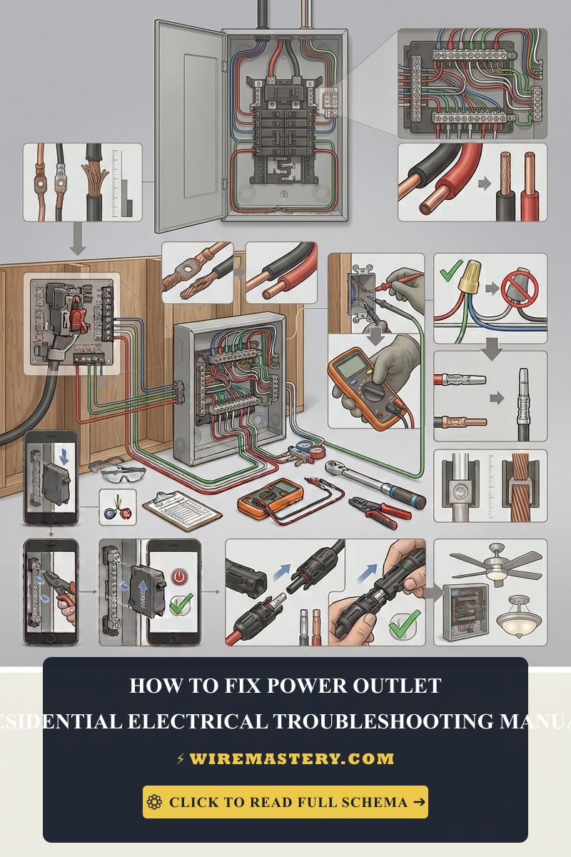
🛠️ Ohmic Loop Analyzer Note: Look closely at the split-phase distribution panel layouts and device assets displayed across our master troubleshooting portfolios. Notice that an alternative trade method to catch a bootleg ground without opening wall boxes is utilizing a high-resolution circuit analyzer. When plugged into a duplex receptacle face, the tester applies a heavy 15-Amp continuous micro-load across the line for a fraction of a second, measuring branch wire voltage drops. If the ground loop impedance reads less than 0.2 Ohms (Ω) while the surrounding wall box lacks a metallic conduit system, the device instantly triggers a false grounding error code, isolating the hidden jumper.
Troubleshooting Common Outlet Failure Modes
- The Connected Receptacle Emits an Intermittent Buzzing Sound: An absolute indicator of a high-resistance terminal connection or a loose backstabbed wire port. The alternating current is actively arcing across loose metal-to-metal contacts inside the casing, generating high thermal heat. Turn off the panel breaker immediately, pull the device forward, cut away the scorched copper tips, and torque your wire loops clockwise around the side screws.
- The GFCI Reset Button Fails to Click or Latch Open: This behavior indicates a reversed Line/Load installation error or internal solid-state component blowout from a historical lightning surge. If you accidentally attached your incoming panel power wires onto the bottom terminal screws stamped LOAD (which are reserved exclusively for daisy-chaining downstream rooms), the internal logic chips will lock out the mechanism. Swap the wire runs back to the LINE terminals to clear the loop.
- An Outlet Registers a “Reverse Polarity” Light Code Code: This diagnostic code confirms that the current-carrying paths have been flipped during hardware reassembly. The black hot wire has been secured to the silver screw and the white neutral attached to the brass screw, leaving the wide slot live. Isolate power and correct the wiring orientation immediately to mitigate severe shock hazards.
National Electrical Code Receptacle Integrity Regulations
Adhering to strict electrical installation codes shields your home investment, maintains property valuation, and ensures full insurance compliance. The National Electrical Code strictly regulates residential outlets, device protective parameters, and ground fault boundaries under NEC Article 406 (Receptacles, Cord Connectors, and Attachment Plugs (Caps)):
- Replacing Ungrounded Receptacles (NEC 406.4(D)(2)): When existing non-grounding two-wire outlets are replaced, the code strictly prohibits installing a standard three-prong grounding outlet unless a true equipment grounding path is routed back to the panel bar, or the branch is protected via a code-compliant GFCI device labeled explicitly as “No Equipment Ground.”
- Tamper-Resistant Safety Mandates (NEC 406.12): All newly installed or replaced residential receptacles inside habitable rooms must be certified as Tamper-Resistant (TR), incorporating internal plastic spring shutters behind the slot faces to prevent foreign objects from making contact with live line components.
For the NFPA 70 provisions relevant to this guide on How to Fix a Power Outlet: Troubleshooting Bootleg Grounds, consult the Official NFPA 70: National Electrical Code (NEC).
Conclusion
This article explains receptacle system bonding geometries, exposing hidden bootleg grounds using high-accuracy digital multimeters, and executing legal no-ground upgrades through certified Tamper-Resistant GFCI components transforms basic household electrical repairs into safe, troubleshooting milestones. By keeping wire diameter selections aligned with overcurrent limits, erasing illegal neutral-to-ground parallel loops, and enforcing strict compliance with NEC Article 406 labeling enforcements, you build an exceptionally resilient, safe residential grid environment. For final checks, complete panel power isolation safety checks before opening wall boxes, deploy CAT III certified diagnostic meters, and execute every terminal test step with safety-first precision.







