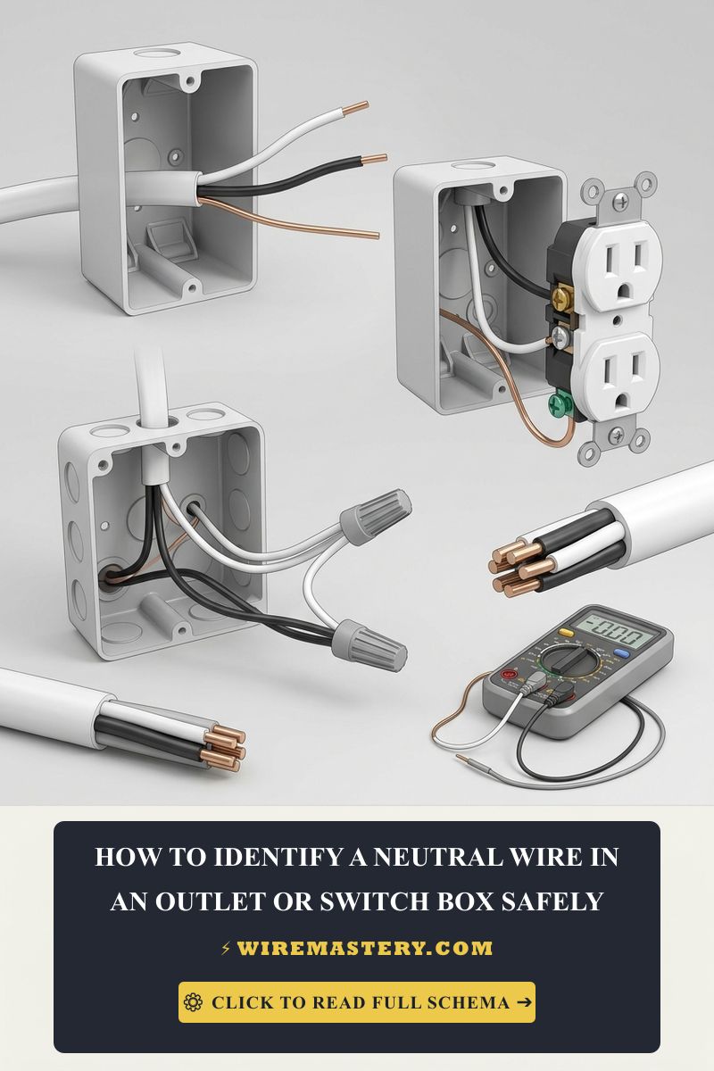
Identify an Unmarked Neutral Wire Safely
Isolating and verifying the grounded neutral conductor inside a legacy residential switch cavity or an unlabelled junction box enclosure demands a rigorous diagnostic protocol that tracks low-impedance pathways back to the primary service panel board. In standard modern North American electrical systems framed under uniform code compliance, identification is visually straightforward due to color-coded PVC insulation. However, when retrofitting advanced automation layers or smart devices inside vintage properties constructed before modern standards, technicians frequently encounter weathered cloth-jacketed conductors where decades of localized thermal heat and carbon dust have completely blackened all wire coatings. Relying on visual assumptions or raw color indexing inside an unmapped box is a hazardous trade practice that can trigger catastrophic dead short circuits or create dangerous continuous ground-loop currents.
This reference manual outlines the precise mechanical processes required to map unlabelled neutrals, differentiate true return paths from capacitive phantom lines, and execute safe diagnostic steps under live voltage and unpowered frameworks.
Core Circuit Identification Parameters
Before uncoupling continuous wire nut bundles or inserting multitester probes into an energized box enclosure, decode these foundational engineering boundaries:
- The Zero-Potential Reference Rule: Under stable grid conditions, a true grounded neutral conductor carries an electrical potential floating at or incredibly close to 0 Volts relative to the structural earth ground bar. It serves exclusively as the current-carrying return pathway to complete the single-phase 120V AC loop back to the utility transformer panel block.
- The Switch Leg Trap: A loose white wire tucked into a switch box is not automatically a neutral line. In legacy ceiling-fed switch loops, the white wire was legally deployed to drop continuous line hot power down to the switch yoke, meaning it carries a lethal 120V AC potential whenever the branch breaker is engaged.
- The High-Impedance Leakage Prerequisite: Digital diagnostic meters with standard high input impedance can register false voltage fields induced from adjacent active wires running inside the same wall conduit. Field operators must utilize advanced testing methodologies to collapse these ghost tracks cleanly.
Technical Materials & Legacy Wire Mapping Toolkit Checklist
Safely sorting oxidized cloth insulation layers and executing micro-ampere terminal audits requires specific category-certified field instruments and safety gear:
| Electrical Diagnostic Tool | Primary Engineering Purpose & Safety Rating |
|---|---|
| True RMS Digital Multimeter | Must feature an integrated Low Impedance (LoZ) setting to erradicate floating ghost potentials. |
| Non-Contact AC Voltage Tester | High-sensitivity proximity sensor to verify a 100% de-energized box workspace. |
| 1000V Insulated Linesman Pliers | Hardened jaws to safely pull, straighten, and isolate stiff copper leads inside cramped boxes. |
| Ratcheting Terminal Strippers | Calibrated to cleanly strip insulation off #14 AWG and #12 AWG solid copper cores. |
| Class 00 Dielectric Rubber Gloves | Certified high-density rubber wraps rated to block up to 500V AC continuous contact tracks. |
Sizing Conductor Cross-Sections & Amperage Load Boundaries
When executing a repair or re-identifying a raw wire core to supply an automated smart module, you must match your conductor parameters to the strict mandates of NEC Article 310.16:
- 14 AWG Solid Copper Conductor (15-Amp Circuit Limit): The most common residential lighting profile. At room temperature (20°C), a healthy 100-foot loop of solid #14 AWG copper wire should display a nominal unpowered resistance value of roughly 0.51 Ohms.
- 12 AWG Solid Copper Conductor (20-Amp Circuit Limit): Heavy-duty branch profile. Required across kitchen small appliance branch circuits (SABC) and dedicated laundry loops. It exhibits a baseline resistance parameter of approximately 0.32 Ohms per 100 feet.
Technical Phase 1: Live Voltage Matrix Auditing on Unlabelled Wires
To safely track down and verify which unlabelled conductor core is the true grounded neutral loop using live system potentials, you must fully reverse the faulty logic of unpowered voltage tests and follow this strict trade testing protocol:
1. Drywall Box Preparation and Disassembly
Turn off the circuit power at the primary panel box temporarily to guarantee safe physical handling conditions. Back out the faceplate and device mounting screws using your insulated drivers. Pull the receptacle or switch yoke forward out of the box cavity carefully. Separate all interconnected wire leads so that their raw copper ends or lateral terminal screws float completely isolated in mid-air, away from each other and the metal box walls.
2. Restoring Branch Line Power Safely
Ensure no loose tools, family members, or bare skin surfaces are contacting the exposed wire array. Return to your main distribution panel and turn the circuit breaker back to the full “ON” position. This restores live nominal line-voltage potential directly across the workspace wires.
3. Executing the Three-Point AC Voltage Testing Matrix
Take your CAT III certified True RMS digital multimeter and rotate the dial to the standard AC Voltage setting (V AC). Ensure the black lead sits inside the COM port and the red lead rests inside the VΩ port. Probe the unlabelled wires following this strict logical sequence:
- Locate the Line Hot Conductor: Probe across the unlabelled wire ends using your ground wire or the edge of a grounded metallic gang box as a reference point. The single wire that displays approximately 120V AC on the screen is your active Line Hot Conductor. Mark it with a wrap of black electrical tape immediately.
- Test Configuration A (Hot to Suspected Neutral): Keep your red multimeter probe locked onto that verified Hot wire core. Touch your black multimeter probe to the second unlabelled wire line you are auditing.
- The System Reading: If the digital display screen registers a stable nominal potential of approximately 120V AC, this reading proves the loop is fully complete, confirming the second wire is a true Grounded Neutral Conductor.
- Test Configuration B (Neutral to Equipment Ground): Move your red multimeter probe off the hot wire and place it onto the newly identified neutral wire core. Keep the black probe locked onto the bare copper grounding wire or the grounded steel box wall.
- The System Reading: The multimeter screen must display an absolute 0V AC parameter (or a minor fractional reading below 0.5V AC induced by standard wire impedance). This low voltage verification proves the wire maintains full bonding parameters back to the main service entrance panel grounding bus bar.
Technical Phase 2: Unpowered Continuity Mapping for Legacy Enclosures
If you are auditing an older property where local safety engineers prohibit live line-voltage diagnostics, apply this alternative unpowered resistance tracking framework to isolate true neutral lines with 100% precision:
1. Hard Panel Isolation and Verification
Navigate to your property’s main service distribution box and toggle the branch circuit breaker completely off. Verify that the system reads an absolute 0V AC state across all unlabelled terminal wires using your non-contact voltage tester before touching raw copper with your fingers.
2. Setting Up the Multimeter for Ohmic Tracking
Rotate your digital multimeter dial to the Continuity setting (indicated by an audible Speaker/Beeper or Ohms Ω symbol). Touch your two testing probes together directly; the meter should emit a continuous loud high-pitched beep and display a resistance reading close to 0.0 Ω, verifying the testing instruments are working flawlessly.
3. Measuring Resistance to the Structural Ground Path
Because the National Electrical Code requires that the neutral bus bar and the grounding bus bar be physically tied together (bonded) exclusively inside the primary service entrance panel board enclosure, every true neutral wire maintains direct metal-to-metal continuity back to the ground track.
- Place your black multimeter probe onto a known, verified structural ground track (such as the bare copper wire or the side edge of a grounded metallic gang box).
- Touch your red testing probe to the unlabelled conductors one by one.
- Analyze the Digital Ohmmeter Display:
- The Line Hot Conductor: The meter will remain silent and display an infinite open-loop message (O.L.), confirming the circuit path is broken back to the open breaker contact points.
- The Grounded Neutral Conductor: The meter will instantly emit a continuous loud beep and register a microscopic resistance reading of less than 2.0 Ω. This low ohmic reading verifies that you have successfully pinpointed the true neutral return line without ever energizing the branch wire.
🛠️ The Shared Neutral Hazard Note: Look closely at the historical multi-wire branch circuit (MWBC) layouts displayed throughout our electrical design portfolios. In properties wired under legacy standards, a single white neutral wire was frequently shared across two completely independent hot circuit phases to reduce materials costs. When tracking unlabelled wires in a multi-gang box, always verify that your neutral line does not register current draws from a sister circuit breaker before uncoupling the wire nut. Disconnecting a shared neutral while its sister phase is actively under load will instantly send 120V shooting through your multimeter, burning out your device logic chips and creating severe localized shock hazards.
Troubleshooting Common Legacy Identification Failures
- The Meter Displays 60V AC Between Hot and Suspected Neutral: This floating parameter confirms an active Broken or Open Neutral Fault. The wire you are probing is physically white or gray, but it has suffered a physical break inside a walls track or a loose splice connection inside an upstream box enclosure. The high-impedance multimeter is picking up a ghost voltage field from adjacent active lines. Switch your digital meter to LoZ mode (Low Impedance); if the reading collapses down to 0V AC, the neutral line is dead and disconnected from the panel return bus bar, requiring a full sequential trace.
- The Suspected Neutral Displays 120V AC Relative to Ground: You are dealing with a dangerous Reversed Polarity installation error or an unmarked hot switch leg loop. A legacy installer has accidentally wired the line hot phase onto the white insulation core down the line without adding a re-identification wrap of black electrical tape. Treat this line as a live phase until you isolate the upstream junction boxes and swap the terminations back to code compliance.
- Upstream sensitive GFCI Breakers Trip During Testing: This occurs when a technician utilizes a cheap, low-end multimeter to conduct live neutral-to-ground current sweeps. Passively bridging a current-carrying neutral return line to the equipment grounding conductor rail leaks micro-amperes to ground, dropping the sensitive panel breaker offline. Always execute resistance matrices on fully de-energized, isolated circuit segments.
National Electrical Code Grounded Conductor Regulations
Adhering to strict electrical installation codes shields your home investment, maintains property valuation, and ensures full insurance compliance. The National Electrical Code strictly regulates general grounded conductors, device identification frameworks, and wire markings under NEC Article 200 (Use and Identification of Grounded Conductors). Use those grounded-conductor rules when identifying an unmarked neutral safely.
- Mandatory Color Identification (NEC 200.6): Grounded neutral conductors of #6 AWG or smaller must be continuously identified by an outer white or gray finish along their entire structural run lengths. Re-identifying black wires as neutrals using white tape is strictly prohibited on small residential branches.
- Re-Identification of White Conductors (NEC 200.7(C)): If a white conductor inside a multi-conductor cable is deployed to act as an ungrounded hot line (such as dropping power down a switch loop), its insulation tip must be permanently re-identified using black or red electrical tape at every accessible splice termination.
For the NFPA 70 provisions relevant to this guide on Identify an Unmarked Neutral Wire Safely, consult the Official NFPA 70: National Electrical Code (NEC).
Conclusion
This guide covers executing live line-voltage analysis and unpowered resistance continuity tracking transforms complex legacy wire identification into a safe, predictable science. By resolving unlabelled conductor puzzles using precise True RMS multitester probes, avoiding dangerous shared neutral shortcuts, and tracking your white neutral paths in strict compliance with NEC Article 200 standards, you build a resilient, commercial-grade electrical framework. For final checks, complete panel breaker power isolation safety checkups, utilize CAT III multimeters, and execute every terminal test step with safety-first precision.







