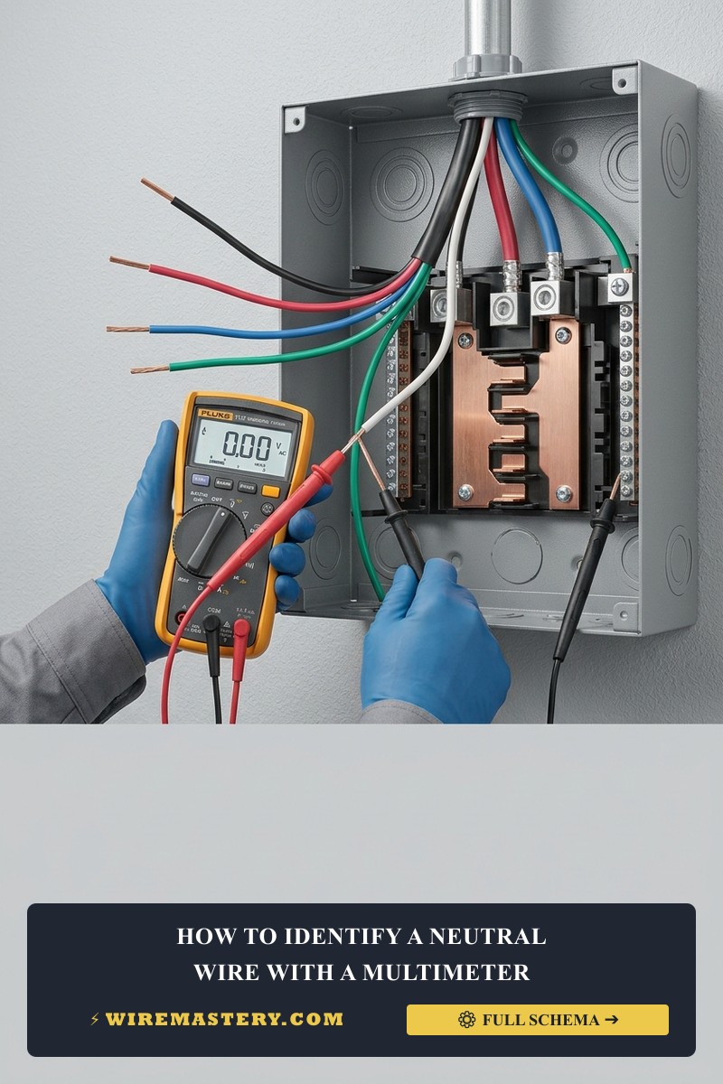
How to Identify a Neutral Wire with a Multimeter: Contractor Guide
Accurately identifying and verifying the grounded neutral conductor inside a residential electrical junction box or multi-gang service enclosure is a foundational diagnostic requirement for executing safe device retrofits, smart automation integrations, and luminaire extensions. Operating as the essential return current pathway, the neutral wire completes the low-impedance electrical circuit loop back to the primary main distribution panel board, allowing single-phase alternating current (AC) loads to function continuously. However, tracking this line requires strict technical auditing; relying blindly on insulation dye coatings can lead to catastrophic hardware destruction or dangerous shock hazards if an undocumented switch-leg loop is actively miswired.
This diagnostic manual outlines the exact mechanical steps to isolate line potentials, execute live voltage verification tests, and complete unpowered resistance continuity tracking using an auto-ranging digital multimeter.
Core Circuit Identification Parameters
Before inserting your multimeter testing probes into any energized enclosure cavity, decode these foundational parameters:
- The Return Potential Threshold: A functional, code-compliant neutral conductor carries an electrical potential floating at or incredibly close to 0 Volts relative to the structural earth ground bar.
- The Shared Neutral Pitfall: In legacy multi-wire branch circuits (MWBCs) operating under older construction standards, a single neutral conductor may be shared across two independent hot phases. Severing or disconnecting a shared neutral while the hot conductors are energized will instantly create an unbalanced high-voltage condition, destroying downstream micro-automation components.
- The True RMS Prerequisite: When measuring low-voltage signal baselines or tracking lines contaminated by non-linear electronics, your testing instrument must feature True RMS diagnostic sensing to avoid false, skewed voltage artifacts.
Technical Materials & Diagnostic Testing Toolkit Checklist
Safely opening energized junction enclosures and executing microscopic terminal readings requires specific insulated trade instruments and safety equipment:
| Electrical Auditing Tool | Primary Engineering Purpose & Safety Threshold |
|---|---|
| Digital Auto-Ranging Multimeter | Must be rated for Category III (CAT III 600V) minimum to safely withstand transient industrial spikes. |
| Non-Contact AC Voltage Detector | Audibly monitors the workspace perimeter to trace live hot conductors before bare skin contact. |
| 1000V Insulated Needle-Nose Pliers | Used to gently manipulate high-density wire bundles within deep plastic or metal gang boxes. |
| Insulated Hand Screwdriver Set | Cushion-grip drivers certified under ASTM F1505 standards to back out terminal screws safely. |
| ANSI-Rated Safety Glasses & Gloves | Baseline personal protective layer guarding against hazardous arc-fault eye damage or flash burns. |
Sizing Conductor Gauges & Jacket Color Code Standards
To prevent thermal heat accumulation and maintain full circuit isolation behind finished drywall sheets, you must understand the legal cross-section parameters and standard field conventions assigned to North American electrical systems:
Standard Residential Wiring Identification Matrix
| Conductor Designation | Standard US Insulation Color | Required Wire Size (AWG) | Circuit Ampacity Limit |
|---|---|---|---|
| The Grounded Neutral | White or Light Gray | #14 AWG / #12 AWG Solid | Matches Overcurrent Breaker Limit |
| The Ungrounded Line Hot | Black or Red | #14 AWG / #12 AWG Solid | 15 Amps (White Romex) / 20 Amps (Yellow) |
| The Equipment Ground | Bare Copper or Green | Included in NM-B Sheath | Sacrificial Safety Return Track Only |
🚨 Contractor Field Warning: The Color Illusion Under NEC Article 200.6, continuous white or gray insulation layers must be reserved exclusively for grounded neutral conductors. However, legacy installers frequently re-assigned white conductors inside 14/2 Romex cables to act as hot switch legs without wrapping the insulation tip with black electrical tape. Always verify functions using your multitester rather than assuming structural wire capabilities based on color codes alone.
Technical Phase 1: Live Line-Voltage Identification Protocol
To track down and verify an unlabelled neutral wire using live electrical potential parameters, you must reverse the faulty logic of unpowered testing and follow this strict field safety testing protocol:
1. Enclosure Opening and Separation
Turn the circuit breaker off temporarily to ensure safe physical entry into the workspace. Remove the decorative plastic faceplate and back out the device mounting ears using your insulated screwdrivers. Pull the outlet or switch body forward out of the wall enclosure. Carefully separate the conductors so that no bare copper tips or lateral terminal screws touch each other or the surrounding metal walls.
2. Energizing the Branch Loop Safely
Ensure no people or loose tools are touching the exposed electrical array. Turn the primary circuit breaker back ON at the main panel board to restore active line-voltage potential to the workspace area.
3. Setting Up the Multimeter
Take your digital multitester and rotate the dial to the AC Voltage setting (V AC). Ensure the testing leads are plugged into the correct ports: the black common lead into the COM slot and the red lead into the V/Ω slot. Select an auditing range higher than the expected line capacity (minimum 200V AC or utilize an auto-ranging device).
4. Executing the Live Voltage Measurement Matrix
To isolate the true neutral wire from line hot elements and sacrificial grounding wires, touch your testing leads to the raw copper conductor terminals following this precise logic sequence:
- Test Configuration A (Hot to Suspected Neutral): Place one testing probe onto the exposed metal part of the identified Hot wire (typically Black) and the second probe onto the wire you suspect is the neutral (White).
- The System Reading: The multimeter screen should display approximately 120V AC (or the nominal line voltage of your local grid). This reading confirms the loop is complete and that the second wire is a true neutral.
- Test Configuration B (Hot to Equipment Ground): Keep the first probe on the Hot wire and move the second probe to the bare copper or green grounding conductor.
- The System Reading: The multimeter screen must also display approximately 120V AC. This proves that the grounding track is unbonded inside the junction box but maintains full fault-path continuity back to the primary main distribution panel board.
- Test Configuration C (Neutral to Equipment Ground): Place one testing probe onto your newly verified neutral conductor and the second probe onto the bare grounding wire.
- The System Reading: The multitester screen must display 0V AC (or a microscopic phantom reading below 0.5V AC induced by normal line impedance). This confirms that the neutral wire is at zero potential relative to the earth ground.
🛠️ Contractor Blueprint Testing Note: Look closely at the electrical diagnostic layouts printed across our trade testing portfolios. Notice that when troubleshooting legacy junction boxes where years of thermal carbon dust or paint overspray have fully blackened the wire insulation layers, relying on color indicators is impossible. If multiple wires read 120V relative to each other, stop working immediately; you are likely dealing with a dual-phase 240V multi-wire branch circuit grid or a reversed polarity installation error that requires upstream panel isolation before proceeding.
Technical Phase 2: The Safe Unpowered Resistance Continuity Test
If you are working inside an environment where executing live electrical potential testing is highly dangerous or prohibited by local site management rules, apply this alternative unpowered resistance tracking protocol:
1. Hard Isolation and Verification
Navigate to your property’s main service distribution box and toggle the circuit breaker completely off. Verify that the system reads an absolute 0V AC state across all terminal wires using your non-contact voltage tester before touching raw copper with your fingers.
2. Setting Up the Multimeter for Resistance
Rotate your digital multimeter dial to the Continuity setting (indicated by an audible Speaker/Beeper or Ohms Ω symbol). Touch your two testing probes together directly; the meter should emit a continuous loud high-pitched beep and display a resistance reading close to 0.0 Ω, verifying the testing instruments are working flawlessly.
3. Measuring Resistance to the Structural Ground Path
Because the National Electrical Code requires that the neutral bus bar and the grounding bus bar be physically tied together (bonded) exclusively inside the primary service entrance panel board enclosure, every true neutral wire maintains direct metal-to-metal continuity back to the ground track.
- Place your black multimeter probe onto a known, verified structural ground track (such as the bare copper wire or the side edge of a grounded metallic gang box).
- Touch your red testing probe to the unlabelled conductors one by one.
- Analyze the Digital Ohmmeter Display:
- The Line Hot Conductor: The meter will remain silent and display an infinite open-loop message (O.L.), confirming the circuit path is broken back to the open breaker contact points.
- The Grounded Neutral Conductor: The meter will instantly emit a continuous loud beep and register a microscopic resistance reading of less than 2.0 Ω. This low ohmic reading verifies that you have successfully pinpointed the true neutral return line without ever energizing the branch wire.
Common Diagnostic Mistakes & Pitfalls to Avoid
- Relying Blindly on Floating Neutral Voltages: If an upstream neutral connection is broken or severed inside a walls track, the dead line will float and pick up induced voltages from adjacent hot runs. Measuring a floating line with a high-impedance digital tester can give false readings of 30V to 90V AC. Always cross-verify your circuits using a low-impedance multimeter (LoZ mode) to collapse phantom voltages cleanly.
- Assuming the Ground Wire is an Acceptable Neutral Substitute: Never connect your device current-carrying neutral return terminals directly onto the bare safety ground wire. While this hack will complete the circuit and make the device power up, it forces active return current to run continuously across your home’s exposed metal chassis parts and wall box screws, creating a massive, code-violating shock hazard.
- Failing to Check for Shared Multi-Wire Neutral Loads: Always lock out both breakers of a dual-phase branch circuit before testing. Disconnecting a neutral lead while a sister phase is running will send 120V shooting through your tester and burn out downstream smart electronics instantly.
National Electrical Code Infrastructure & Identification Rules
Adhering to strict electrical installation codes shields your home investment, maintains property valuation, and ensures full insurance compliance. The National Electrical Code strictly regulates general grounded conductors, device identification frameworks, and wire markings under NEC Article 200 (Use and Identification of Grounded Conductors). Use those identification rules throughout this multimeter-based neutral-wire check.
- Mandatory Color Compliance (NEC 200.6): Grounded neutral conductors of #6 AWG or smaller must be continuously identified by an outer white or gray finish along their entire structural run lengths. Re-identifying black wires as neutrals using white tape is strictly prohibited on small residential branches.
- Device Polarization Rules (NEC 406.4): Receptacles and outlets must be connected to ensure that the wide terminal slot matches the verified grounded white neutral line perfectly, keeping the thread casing of plugged appliances at safe zero potential.
For the NFPA 70 provisions relevant to this guide on How to Identify a Neutral Wire with a Multimeter: Contractor Guide, consult the Official NFPA 70: National Electrical Code (NEC).
Conclusion
This guide covers executing live line-voltage matrices and unpowered continuity tests transforms complex electrical diagnostics into safe, systematic solutions. By resolving unlabelled conductor puzzles using precise True RMS multitester probes, avoiding dangerous safety-ground shortcuts, and tracking your white neutral paths in strict compliance with NEC Article 200 standards, you build a resilient, residential grid. For final checks, complete panel breaker power isolation safety checkups, utilize certified CAT III multimeters, and execute every terminal test step with safety-first precision.







