How to Troubleshoot Smart Thermostat C-Wire Defects (Easy Guide)
Modern smart thermostats offer excellent energy efficiency and home automation integration. However, they require consistent power to operate their digital displays and Wi-Fi radios.
When a system experiences power anomalies, a defect or absence in the 24V Common wire (C-wire) pathway is a frequent suspect. Understanding these low-voltage control loops allows homeowners to perform basic, non-invasive troubleshooting before consulting an HVAC professional.
Potential Symptoms of a Defective C-Wire Pathway
C-wire issues can manifest in various ways, often mimicking control board glitches or equipment short-cycling. The following table outlines common operational symptoms and their possible electrical causes. These scenarios are non-definitive guidelines and should be treated as diagnostic starting points rather than absolute conclusions.
| Thermostat Symptom | Possible Electrical Cause | Recommended Non-Invasive Action |
|---|---|---|
| Blank, dark, or flickering screen | Interrupted 24V AC continuous loop or open safety switches | Check system power switches and measure voltage at the wall plate. |
| Intermittent Wi-Fi dropouts | Insufficient power delivery due to micro-current power stealing | Verify if a dedicated common wire is present and connected. |
| System short-cycling (turning on/off rapidly) | Potential floating voltage reference or control circuit interference | Cease operation immediately and request a professional inspection. |
Step-by-Step Multimeter Sweep Protocol: Tracking the Voltages Safely
When an unboxed smart thermostat discovers only four conductor lines leaving the finished wall cavity (typically Red, White, Yellow, and Green), executing a low-voltage multimeter verification sweep helps locate a viable common path.
Technical teams trace potential differences directly at the furnace control board terminals to prevent introducing an accidental cross-phase ground fault.
Follow this rigid diagnostic testing sequence using your True RMS digital multi-tester to verify your low-voltage control lines safely:
1. Isolating the Low-Voltage Control Infrastructure
- Move to the building’s main electrical distribution panel and locate the circuit breaker supplying power to the indoor furnace or air handler unit. Flip the breaker switch to the full OFF position.
- Navigate to the HVAC equipment closet. Remove the panel screws securing the upper blower access door.
- Locate the centralized low-voltage terminal strip on the furnace control board. This terminal cluster is stamped with clear identification lettering alignments: R, C, W, Y, and G.
2. Executing the Voltage Differential Sweep
- Ensure the blower access panel door is fully reinstalled and securely attached to the cabinet framing. The safety door interlock switch must be naturally compressed by the closed door panel.
- Restore line power at the main electrical panel breaker face. The HVAC control motherboard is now safely energized with low-voltage alternating current inside its sealed enclosure.
- Move to the thermostat wall location in the living space to perform safe measurements down the cable run. Rotate your digital multimeter selector dial to AC Voltage mode (V AC). Do not select DC Voltage, as HVAC transformer control loops operate exclusively on alternating current.
- Place your Black testing probe firmly onto the wire core connected to the C (Common) terminal. Touch your Red testing probe to the wire running from the R (24V Hot) terminal:
- A Healthy Transformer Output: The multimeter screen parameter must display a clean reading floating between 24V AC and 28V AC. If the screen registers a flat 0V, the internal primary thermal fuse of the transformer block or the control board fuse has ruptured.
- Maintain the Black testing probe on the C wire. Move the Red testing probe sequentially across the remaining operational conductors: W (Heat), Y (Cool), and G (Fan). Under nominal system idle conditions, the multi-tester display screen must register 0V AC. Any voltage reading floating around 12V to 24V on an idle terminal confirms a leaking control relay array or an active short circuit inside the wire jacket.
Modifying the Infrastructure: Installing a 4-to-5 Wire Common Adapter
If your structural wall box houses absolutely zero extra wire cores, pulling a brand-new 18/5 thermostat cable through finished drywall tracks can be blocked by structural framing. To resolve this hardware barrier without tearing open plaster layers, technicians deploy an engineered, solid-state C-Wire Add-a-Wire Adapter module.
This technical module multiplexes two separate command signals (typically the cooling call Y and the indoor blower call G) over a single physical copper strand, freeing up an existing conductor line to function exclusively as your clean 24V Common return path.
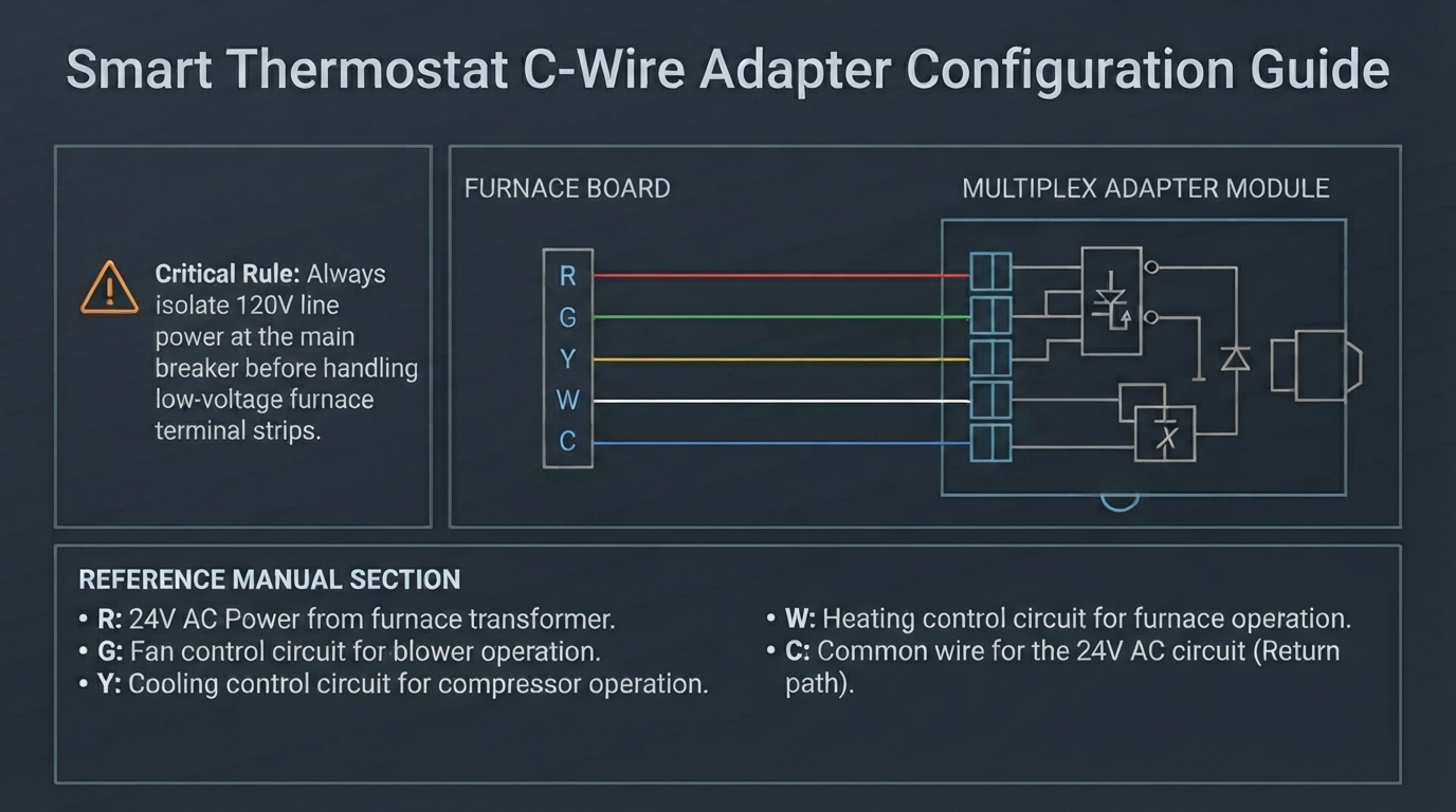
Figure 2: Comprehensive multi-conductor control loop interface utilizing a solid-state multiplex adapter to forge a dedicated 24V Common return pathway across a standard four-wire residential infrastructure.
Step-by-Step Adapter Mounting and Splicing Sequence
Execute this precise mechanical termination layout inside the indoor blower component enclosure:
- Mount the Module Chassis: Switch off the main power breaker. Mechanically anchor the plastic Add-a-Wire adapter box shell onto a clean section of the interior sheet-metal furnace wall casing using a magnetic strip or mounting screws. Never position the module directly across the high-temperature heat exchanger cabinet.
- Terminate the Furnace Side Strands: Connect the module’s pre-stripped wire harness leads directly onto the matching terminal screws of the furnace control matrix: land the module ground lead onto the C screw, the power lead onto the R screw, and the signal leads onto the Y and G inputs.
- Repurpose the Existing Wall Conductor: Disconnect the original Green fan wire (G) from the furnace board lug. Splice it directly onto the combined output wire tracking leading out from the adapter block using an insulated wire nut casing.
- Wire the Thermostat Wall Plate: Move into the living space. Terminate the original Green wire onto the specialized K or Combined terminal input of your smart thermostat backing frame. Take the wire that originally handled the cooling call and land it onto the C terminal pad. Your low-voltage circuit loop is now structurally closed.
Advanced Troubleshooting of Low-Voltage Controls
- The Smart Thermostat Enclosure Clicks Continuously But the Fan Fails to Initialize: This operational breakdown confirms an active Impedance Drop inside the adapter relay circuits. Measure line drops across the K terminal and the C ground plane during a live call for fan execution. Any drop falling below 21V AC will fail to hold the physical furnace induction contacts shut, requiring you to clear any high-resistance oxidation deposits on legacy terminal screws.
- The 3-Amp Control Board Fuse Ruptures the Second the Thermostat Boots: An immediate warning for a Hard Phase-to-Ground Short Fault. This behavior indicates that an operator accidentally crossed the 24V Hot (R) line directly onto the Common (C) line path during wall-plate installation. De-energize the complete panel enclosure instantly, deploy your multimeter in Continuity Mode (Audible Beep), and test all copper filaments against the metal chassis framing wall to isolate the insulation tear before seating a fresh automotive-grade fuse.
For full technical definitions, conduit filling tolerances, and low-voltage electrical updates, consult the Official NFPA 70: National Electrical Code (NEC).
Frequently Asked Questions: C-Wire Troubleshooting & Validation
Can I use the G-Wire as a C-Wire instead of buying an adapter?
Yes, you can repurpose the G (Fan) conductor to act as your 24V Common line, but you will lose independent manual fan control. To execute this setup safely, disconnect the original green wire from the G terminal on both the thermostat wall plate and the furnace control board, landing it directly onto the C terminal blocks. Then, install a physical copper jumper wire between the Y (Cooling) and G (Fan) terminals on the furnace board. This ensures that whenever the thermostat calls for cooling, the indoor blower motor engages concurrently.
What happens if I connect the R wire directly to the C terminal by mistake?
Doing so creates an immediate, low-impedance dead short circuit across the secondary winding of the HVAC step-down transformer. The moment line voltage is restored, the massive current surge will instantly rupture the protective automotive-grade 3-Amp or 5-Amp blade fuse mounted on the furnace control board. If the control board lacks an integrated fuse block, the isolation transformer windings will experience a rapid thermal breakdown and melt within seconds.
Is it safe to pull power from an external 24V plug-in wall transformer?
Yes, deploying an independent external 24V AC isolation transformer is a code-compliant method to power a smart thermostat, provided you follow strict phase-isolation boundaries. When utilizing a separate plug-in transformer asset, you must run its two current-carrying leads directly to the RC and C terminals on the thermostat backplate framework. You must explicitly remove the factory copper jumper clip bridging the RC and RH terminals to prevent a destructive cross-phase short circuit.
Why does my smart thermostat screen flicker or lose Wi-Fi signal intermittently without a C-wire?
This operational breakdown is caused by the device failing to steal enough parasitic current during active heating or cooling execution states. When a thermostat operates without a common line return path, it tries to trickle charge its internal lithium battery pack by leaking tiny current pulses through the heating or cooling relay coils. If the HVAC system runs continuously during an extreme weather day, the thermostat’s internal battery will completely drain, causing the screen to flash or triggering a total software system reboot.