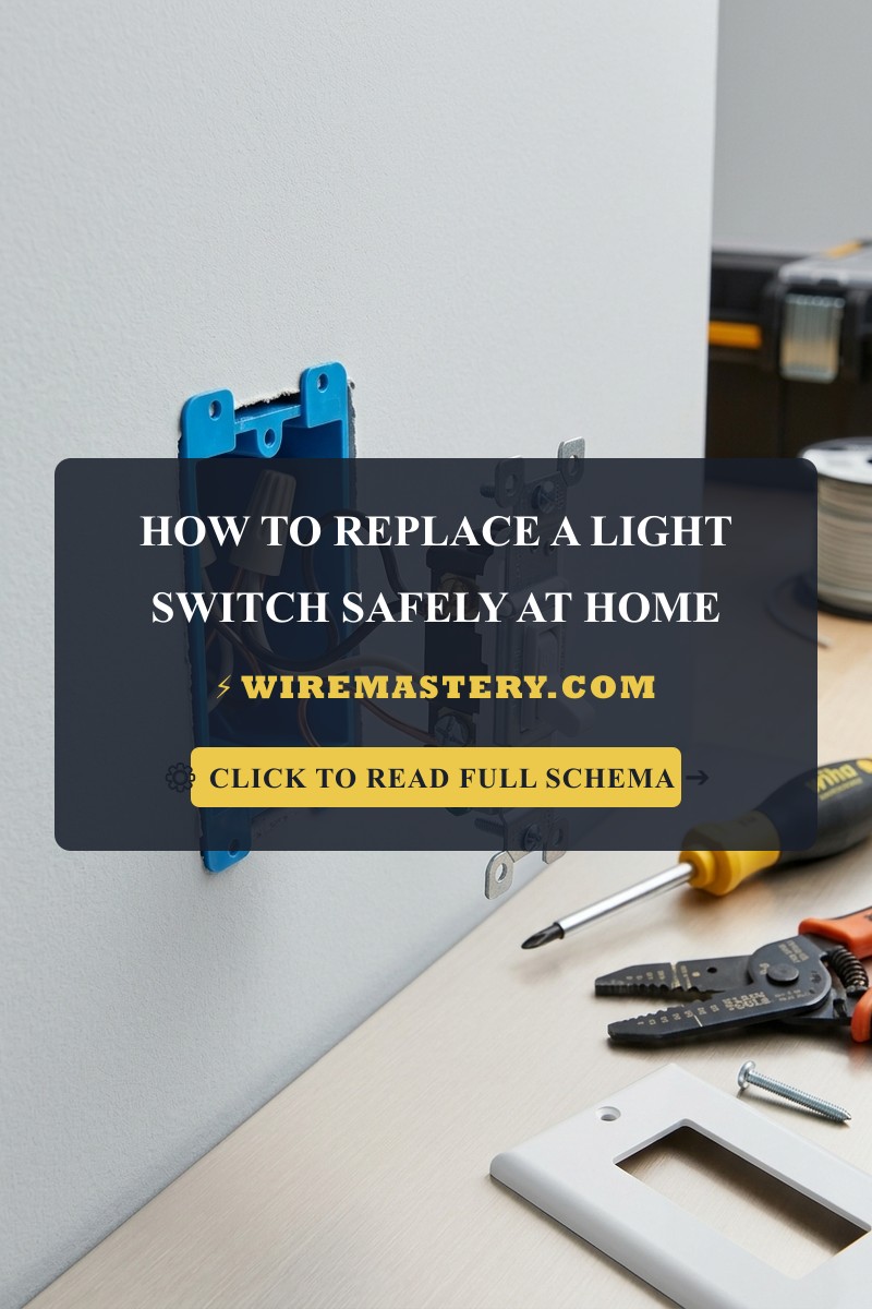
How to Replace a Light Switch Safely: Contractor Manual
Introduction
Executing a reliable, code-compliant residential light switch replacement or infrastructure hardware swap demands a disciplined understanding of branch circuit continuity, spring-loaded toggle kinetics, and terminal isolation protocols. Wall switches function as the primary structural interface separating a property’s users from raw alternating current (AC) line potentials. Over thousands of mechanical snapping cycles, internal copper contact points suffer from progressive pitting and atmospheric oxidation. This wear creates high-resistance gaps that manifest through localized humming noises, visible electrical sparks behind the decorative faceplate, or flickering luminaire arrays. For setups driving advanced whole-house automated grids, ensuring your local junction compartments maintain full compatibility with no-neutral smart switch installation architecture solutions prevents inductive current spikes from degrading new device hardware yokes.
This technical manual outlines the physical mechanics of mechanical toggle failures, precise unpowered diagnostic workflows, and personal protective equipment (PPE) requirements.
Core Hardware Replacement Parameters
Before unmounting decorative cover plates or loosening device side terminal screws, decode these essential circuit boundaries:
- The Phase-Only Interruption Rule: Under the strict mandates of the National Electrical Code, a standard single-pole or multi-point wall switch must interrupt exclusively the ungrounded Line Hot conductor (Black or Red). Connecting a grounded neutral conductor (White) directly to a standard toggle terminal screw creates a parallel bridge, causing a dead short circuit explosion inside the wall enclosure the exact millisecond the lever turns on.
- The Toggle Spring Failure Point: When a light switch lever feels loose, mushy, or fails to emit a loud, distinct mechanical click when flipped, the internal steel spring armature has suffered structural fatigue. The contact pads will fail to press tightly together, inducing continuous low-level micro-arcing.
- The Ampacity Rating Match: Installers must cross-verify that the replacement hardware matches the circuit’s primary protection limits. Installing a cheap 15-Amp rated switch onto a high-density 20-Amp small appliance circuit violates building safety standards under NEC Article 404.14.
Technical Materials & Device Replacement Toolkit Checklist
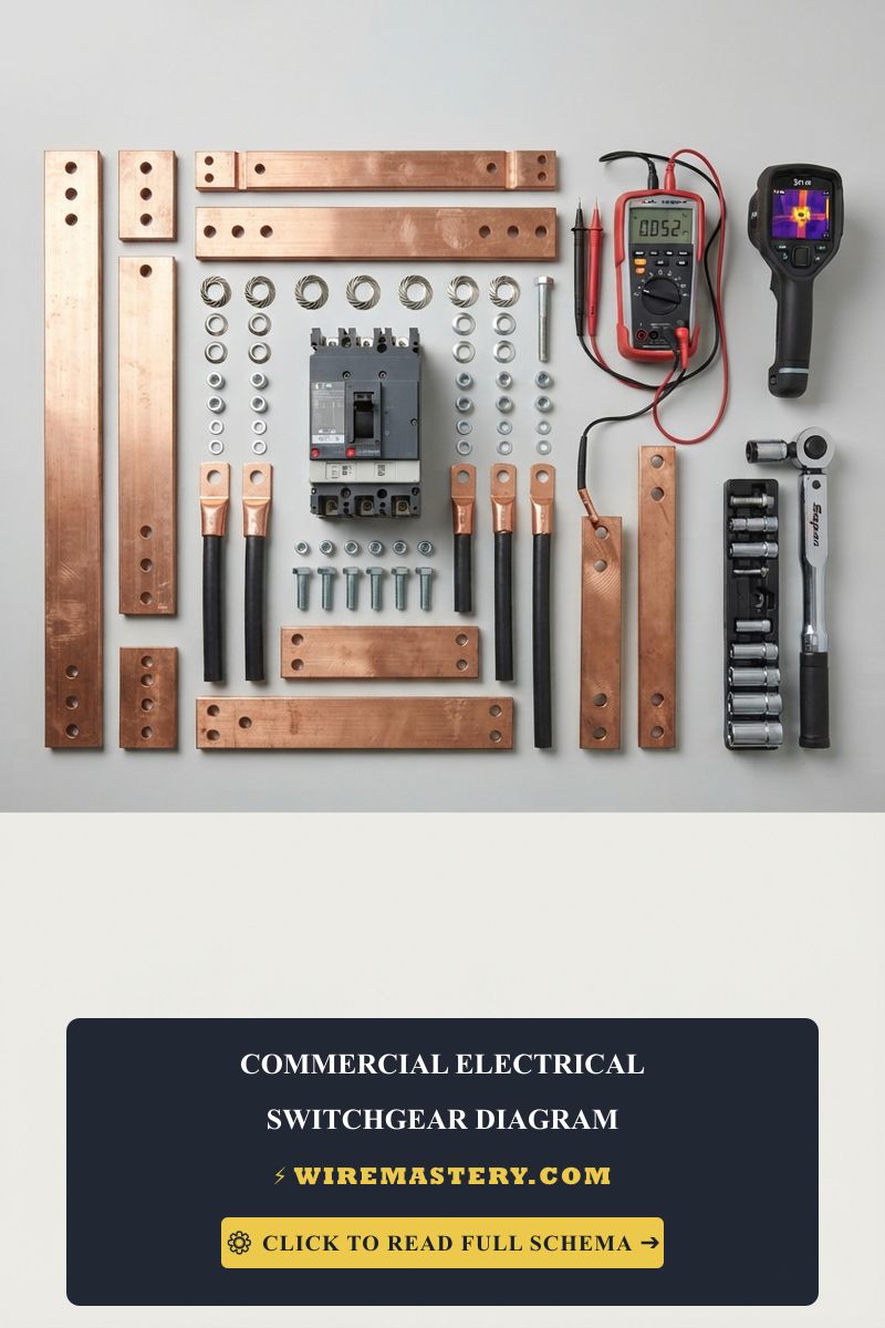
Safely opening energized wall junction cavities and bending solid copper wire terminations requires specific insulated hand tools and testing instrumentation:
| Electrical Replacement Tool | Primary Engineering Purpose & Trade Safety Threshold |
|---|---|
| Non-Contact AC Voltage Tester | High-sensitivity proximity sensor to verify a 100% de-energized box workspace. |
| Digital True RMS Multimeter | Category CAT III 600V certified to test toggle continuity and map traveler paths. |
| Insulated Phillips Screwdriver | 1000V-rated cushioned driver to safely secure switch yokes flush into boxes. |
| Ratcheting Solid Wire Strippers | Calibrated to cleanly remove PVC insulation off #14 AWG and #12 AWG solid copper cores. |
| Ergonomic Needle-Nose Pliers | Formulates clean clockwise solid copper hooks around side terminal screw shanks. |
Conductor Diameters & Terminal Torque Metrics (NEC 404.9)
Selecting an incorrect conductor profile introduces dangerous electrical resistance, leading to progressive insulation decay inside wall cavities. The National Electrical Code strictly regulates branch circuit conductor cross-sections based on nominal overcurrent protection limits. Apply those conductor-sizing rules when replacing the light switch described here.
- 14 AWG Solid Copper Conductor (White Romex Jacket): Sized exclusively for 15-Amp overcurrent breakers. The universal thickness profile deployed for general residential lighting branches supplying multi-fixture arrays.
- 12 AWG Solid Copper Conductor (Yellow Romex Jacket): Sized exclusively for 20-Amp overcurrent breakers. Mandatory if your lighting circuit ties into a shared commercial layout or high-density residential automation subpanel.
- The Side-Screw Loop Rule: Professional contractors avoid using the economy “push-in” or backstabbed wire ports located on the rear casing of cheap switches. Under sustained continuous loads, these internal spring clips lose mechanical tension, creating high-resistance hotspots. Always strip 3/4 inch of insulation, bend the solid copper core into a uniform hook using your needle-nose pliers, loop it clockwise around the side screw shank, and torque the screw tightly.
Technical Phase 1: The Safe Unpowered Toggle Continuity Diagnostic
To verify if a broken light switch has suffered internal contact failure or spring breakdown before uncoupling any conductors, apply this unpowered test sequence:
1. Hard Panel Circuit Isolation
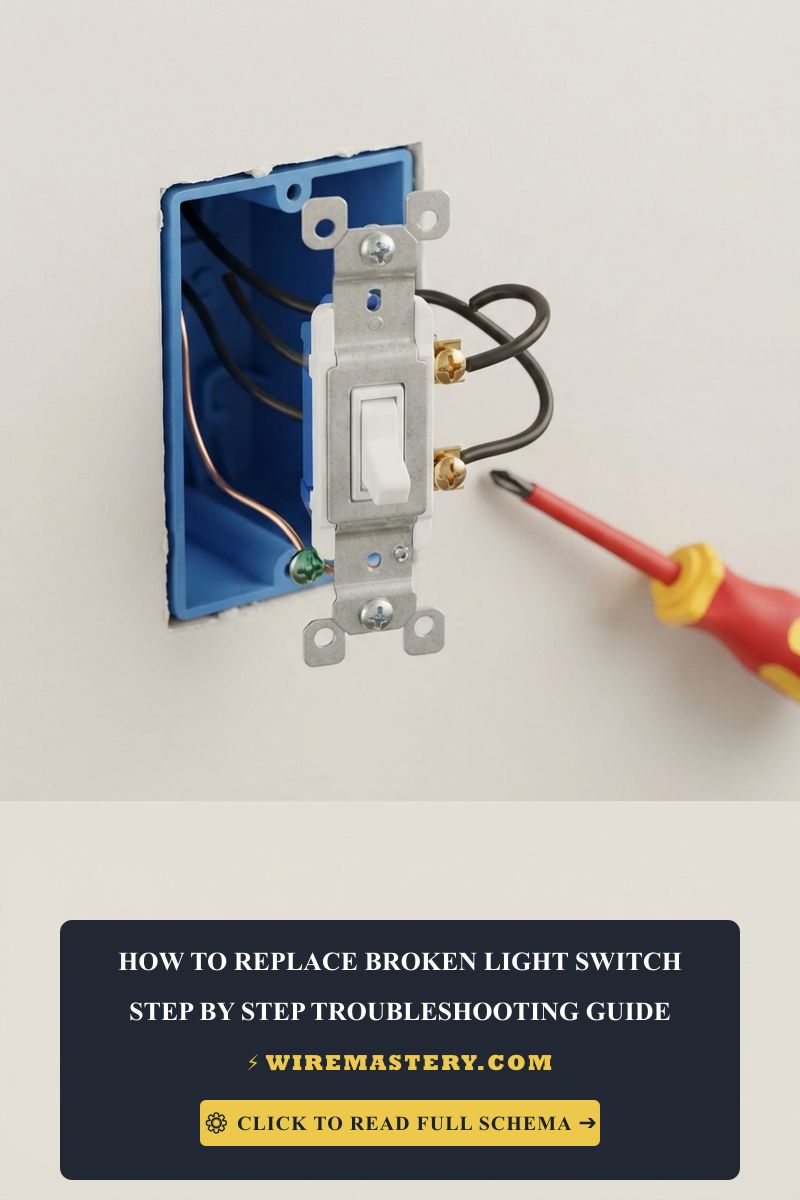
Go to the primary breaker panel block. Turn off and mechanically lock out the circuit breaker toggle supplying power to the target room box. Remove the plastic faceplate cover plate screws. Back out the two device mounting screws holding the switch yoke into the gang box cavity. Pull the switch forward carefully to expose the side terminal screws. Do not touch raw copper tips. Press your non-contact voltage tester against all side screws to confirm an absolute 0V AC state before proceeding.
2. Setting Up the Multimeter for Resistance Testing
Take your digital multimeter and rotate the dial to the Continuity setting (indicated by an audible Speaker/Beeper or Ohms Ω symbol). Touch your two testing probes together directly; the meter must emit a continuous high-pitched beep and display a resistance reading close to 0.0 Ω, confirming your test leads are functional.
3. Measuring the Toggle Contact Loop Resistance
- Flip the switch lever to the absolute “OFF” position. Place one multimeter probe onto the top side brass screw terminal and the second probe onto the bottom brass screw terminal.
- The System Parameters: The digital display must read an infinite open loop (O.L.) and remain completely silent, confirming the contact pads are successfully separated.
- Flip the switch lever to the absolute “ON” position. Keep the probes anchored on the exact same brass screws.
- Analyze the Ohmmeter Data Display: A properly functioning breaker or toggle switch must emit a continuous loud beep and register a resistance reading below 0.1 Ω. If the meter stays silent, registers an infinite open loop (O.L.), or displays a floating resistance value exceeding 1.0 Ω, the internal contact faces have accumulated a heavy layer of non-conductive carbon soot from historical arcing. The switch is internally broken, defective, and demands immediate replacement.
Step-by-Step Field Blueprint: Replacing Single-Pole & 3-Way Wall Switches
To execute a flawless, code-compliant device upgrade, follow these precise physical installation sequences matching your specific device topology:
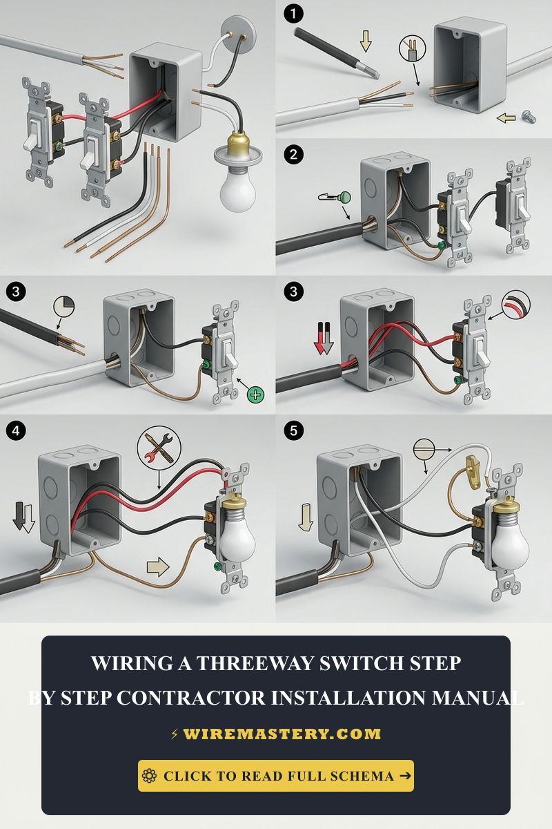
1. Configuration Scenario A: Swapping a Standard Single-Pole Light Switch
A single-pole device manages a lighting load from one unique wall location.
- Verify the branch breaker is turned completely off and locked out. Confirm a true 0V AC state on all side screws using your non-contact tester.
- Unscrew the terminal screws and remove the old switch. You will find two current-carrying wires (typically both are Black, or one Black and one Red hot line). Note that any white neutral wires present inside the box cavity must remain bundled together in the back with a wire nut—never connect a neutral wire to a standard single-pole switch.
- Take your new single-pole switch. Form clean, uniform clockwise hooks on the ends of your hot wires using your needle-nose pliers.
- Loop the incoming Line Hot wire around the bottom brass screw terminal and the outgoing Load Hot wire around the top brass screw terminal. Tighten both side screws firmly with your insulated screwdriver.
- Connect the bare copper or green insulation safety ground wire directly to the green grounding hex screw located on the switch metal yoke strap.
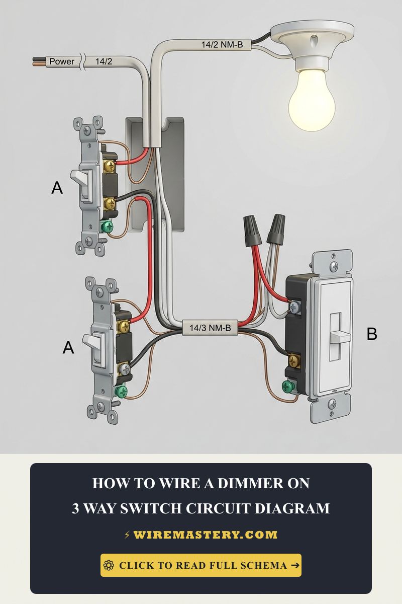
2. Configuration Scenario B: Swapping a 3-Way Light Switch Loop
A 3-way layout controls a lighting branch loop from two separate wall boundaries.
- Isolate the Dark Common Terminal: Before uncoupling any lines from the old broken 3-way switch, locate the dark charcoal-colored terminal screw stamped COMMON. Tag the wire connected to this screw using a wrap of black electrical tape.
- Disconnect all wires. Take your new 3-way switch assembly. Connect your tagged wire directly onto the new Dark Common terminal screw.
- Take the remaining two current-carrying conductors inside the box cavity (the traveler pair, typically Black and Red wires inside 14/3 Romex). Form clockwise loops and secure them directly onto the two lighter brass traveler terminal screws. The positioning of the travelers does not matter, provided they anchor exclusively to the designated traveler blocks.
- Wrap the entire perimeter of the switch casing with two tight layers of high-grade, 600V-rated electrical tape to insulate the exposed side terminal screws fully. Fold the wires flat using an accordion pattern, seat the device straight using your level, and torque the faceplate screws snugly.
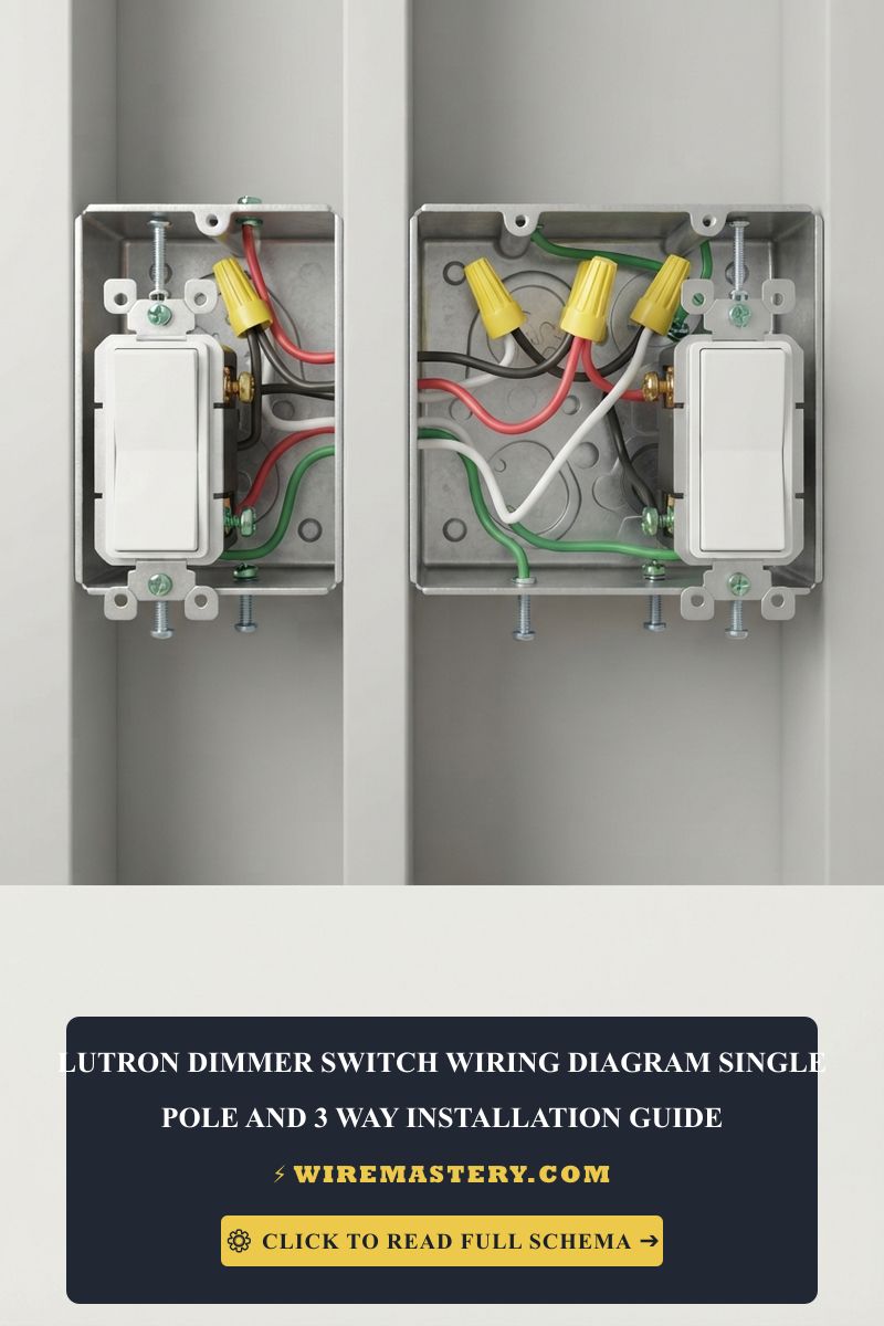
🛠️ Metal Gang Box Bonding Note: Look closely at the split-phase subpanel layouts and terminal assets showcased across our master troubleshooting portfolios. Under the mandates of NEC Article 404.9, if you are installing a new toggle switch inside a metallic gang box enclosure rather than a non-conductive plastic box, you must run a dedicated bare or green copper pigtail jumper from the switch grounding screw directly onto a 10-32 grounded machine screw threaded into the back of the steel box cavity. Relying on the switch mounting ears to make a ground path to the metal box frame violates federal building inspection safety guidelines.
Troubleshooting Common Switch Replacement Failures
- The Switch Lever Spits Sparks or Hums When Toggled: An absolute indicator of a loose side-screw terminal termination. If a conductor wire hook is loose or was wrapped counter-clockwise around the screw shank, flipping the switch will induce continuous carbon micro-arcing. De-energize the panel breaker immediately, pull the switch forward, cut away the charred copper tips, and torque the side screws tightly to exact manufacturer specifications.
- A New 3-Way Switch Layout Works Only When the Opposing Switch points UP: This behavior indicates a crossed Common/Traveler wiring fault. You have accidentally placed one of the alternating traveler wires onto the dark Common terminal screw, or vice versa. Disengage the panel breaker, pull the device, use your auto-ranging multitester in resistance mode to isolate the continuous line/load wire, and re-terminate the tagged core onto the Dark Common lug.
- Upstream sensitive AFCI Breakers Trip Intermittently After Reassembly: Check for an active ground-to-neutral wire pinch. When stuffing high-density wire bundles back into a cramped single-gang wall cavity, an uninsulated bare copper equipment grounding wire can bend and touch a silver terminal screw or an uninsulated neutral splice. This accidental contact leaks micro-currents to ground, dropping the sensitive Arc-Fault panel breaker offline. Wrap the device yoke with high-grade electrical insulation tape to clear the hazard.
National Electrical Code Switch Infrastructure Regulations
Adhering to strict national structural regulations protects your home infrastructure from fire hazards and ensures full property insurance compliance. The National Electrical Code strictly regulates residential switch installations, device grounding, and junction box boundaries under NEC Article 404 (Switches) and Article 314:
- Enclosure Flush Compliance Standards (NEC 314.20): In walls or ceilings constructed of non-combustible materials (such as drywall or plaster), electrical boxes must be installed so that the front edge of the enclosure sits flush with or projects slightly past the finished surface. If the box sits recessed deeper than 1/4 inch, you must install a non-combustible box extender sleeve to prevent arcing sparks from contacting raw timber framing.
- The Mandatory Neutral Presence Requirement (NEC 404.2(C)): Modern electrical codes mandate that a continuous grounded neutral conductor (White wire) must be present at each switch location within residential branch wiring loops. This parameter ensures that future smart home automation retrofits have a built-in neutral return path to power their processors safely without illegally bleeding current down the ground wire.
For the NFPA 70 provisions relevant to this guide on How to Replace a Light Switch Safely: Contractor Manual, consult the Official NFPA 70: National Electrical Code (NEC).
Conclusion
This article explains single-pole and multi-point 3-way switch loops, executing unpowered closed-contact resistance checks using CAT III auto-ranging multimeters, and eliminating high-resistance terminal arcing through clockwise side-screw loops transforms basic home repairs into highly predictable operations. By keeping wire configurations fully aligned with NEC Article 404 phase interruption limits, wrapping terminal screws with premium insulation tape to prevent enclosure shorts, and respecting mandatory subpanel grounding rules, you construct an unshakeable residential grid infrastructure. For final checks, complete panel breaker power isolation safety checkups, deploy ASTM F1505 certified insulated tools, and execute every terminal step with safety-first precision.