How to Replace a Broken Light Switch: Step-by-Step Guide
Replacing a malfunctioning wall toggle switch is one of the most frequent and high-yield residential maintenance projects a homeowner can perform. Over time, internal mechanical spring clips wear out due to continuous friction, leading to weak electrical contacts, localized resistance, or complete terminal dropout. Ignoring an erratic switch does more than disrupt your room lighting; intermittent arcing behind drywall creates a severe and active fire hazard. Mastering how to execute a systematic electrical audit allows you to swap failing devices safely without paying expensive contractor diagnostic fees.
Professional light switch troubleshooting methodologies, exact single-pole wiring configurations, and physical installation procedures aligned with the National Electrical Code (NEC).
Core Circuit Safety Constraints
Before removing any enclosure screws or managing raw branch conductors, establish your operational safety parameters:
- The Single-Phase Hot Break Rule: Standard single-pole light switches do not connect to current-carrying neutral lines. Their sole engineering function is to mechanically break or close the continuous 120V Line Hot wire to control downstream illumination.
- Chassis Grounding Mandates: Under current building codes, every replacement switch must be bonded directly to the equipment grounding conductor to eliminate the risk of faceplate electrification during an internal insulation blowout.
- Terminal Compatibility Limits: Ensure your device rating matches your circuit capacity. Standard residential branches operate on 15-Amp lines, requiring standard 15A toggle hardware.
Technical Materials & Diagnostic Prototyping Toolkit
Executing professional, code-compliant device replacements requires specific electrical hand tools and testing instruments:
| Electrical Trade Tool | Primary Technical Purpose |
|---|---|
| Non-Contact Voltage Tester | Essential safety tool to verify 100% circuit de-energization inside the wall box. |
| Solid Wire Strippers | Calibrated to strip clean insulation off #14 AWG and #12 AWG solid copper cores cleanly. |
| Needle-Nose Pliers | Formulates tight, uniform clockwise terminal hooks to wrap around side screw shanks. |
| Insulated Hand Screwdrivers | Cushion-grip Phillips and flathead drivers to torque terminal blocks without slipping. |
| Digital Clamp Multimeter | Measures true AC voltage thresholds and traces internal mechanical continuity faults. |
The Diagnostics Phase: Troubleshooting a Broken Light Switch
Amateur installers often rush to cut wires before identifying the exact source of a lighting failure. Before purchasing hardware, execute this structured trade diagnostic sequence to confirm if your switch body is genuinely broken:
1. Acoustic and Thermal Fault Screening
Turn the room lighting toggle on and off slowly while listening closely to the wall cavity. If you hear a faint sizzling, cracking, or buzzing noise, the internal contacts are heavily pitted and generating dangerous micro-arcs. Furthermore, if the plastic faceplate feels warm to the touch after running for 20 minutes, turn off the breaker immediately; thermal buildup indicates progressive mechanical terminal decay.
2. The Audible Mechanical Audit
A healthy toggle switch should click with a sharp, crisp mechanical snap when flipped between positions. If the lever feels loose, mushy, or drops into positions without tactile resistance, the internal spring mechanism has snapped. The device is fully compromised and requires complete structural extraction.
3. The Digital Continuity Test (The Absolute Verification)
If the light fixture stays dark but the circuit breaker remains engaged, use a digital multimeter to test the switch core:
- Isolate the power feed at your main breaker panel and pull the switch out of the gang box safely.
- Disconnect the two main conductors from the side terminal screws.
- Turn your multimeter dial to Continuity mode (Ohms/Beeper symbol).
- Place one test probe onto the upper brass screw and the second probe onto the lower brass screw.
- Flip the toggle switch to the “ON” position. If the meter remains silent or registers an infinite resistance reading (O.L.), the internal copper contact plate is oxidized or broken. The device is dead.
Step-by-Step Single-Pole Light Switch Replacement Manual
Once your diagnostics phase confirms an internal hardware failure, follow this systematic field protocol to execute the physical replacement safely:
1. Pre-Installation Isolation Protocol
Locate your property’s primary distribution panel and disengage the specific circuit breaker toggle supplying power to the workspace. Remove the old decorative faceplate screws. Prior to backing out any hardware, press your non-contact voltage tester directly against both side screw terminals to ensure the box cavity reads completely dead (0V AC).
2. Device Extraction and Conductor Inspection
Unscrew the upper and lower mounting ears securing the switch yoke to the gang box framework. Carefully pull the switch forward out of the wall cavity. Use your wire strippers to clip back any brittle, overheated copper ends and expose exactly 3/4 inch of fresh solid copper core. Braid or straighten the wire ends until they are perfectly smooth.
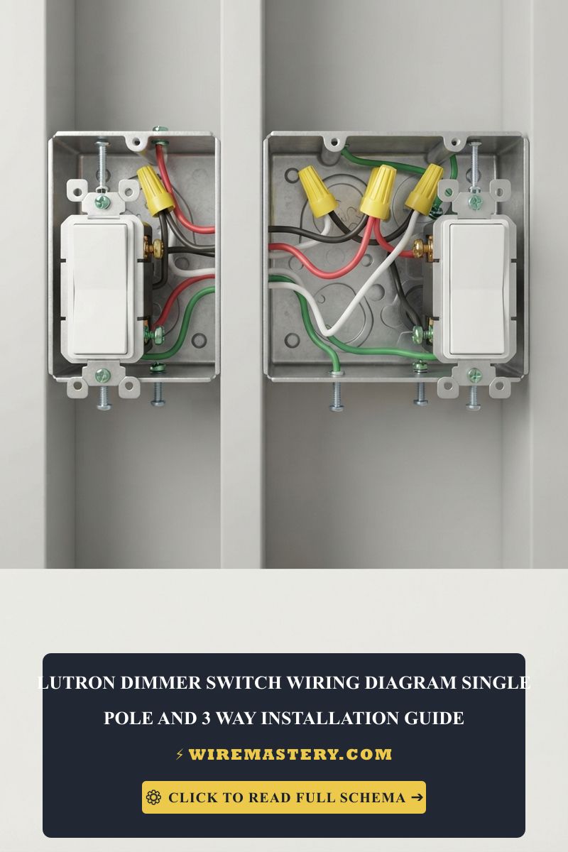
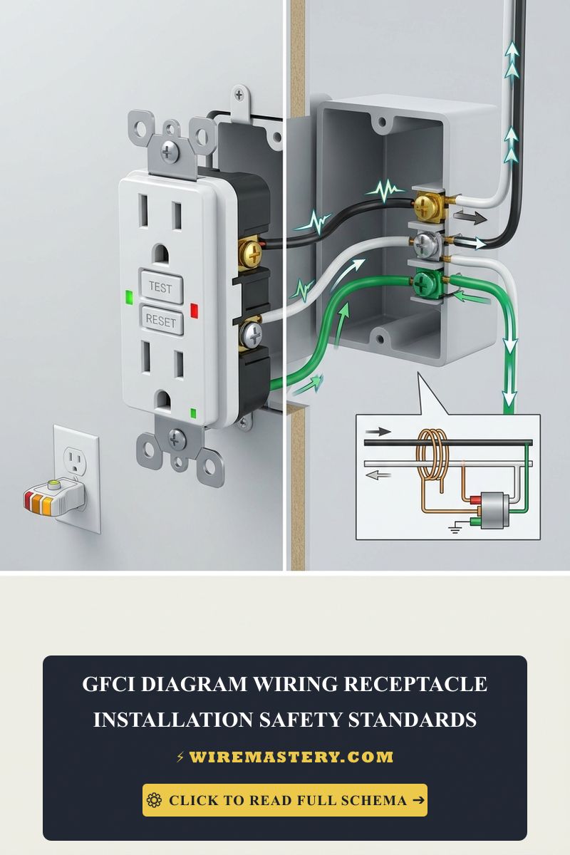
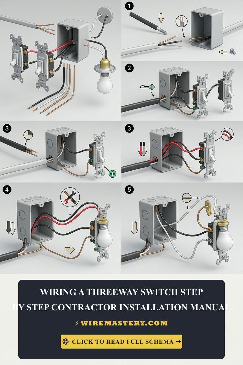
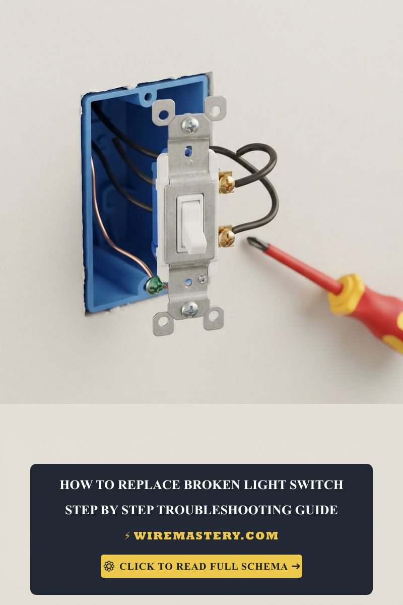
🛠️ Contractor Visual Note: Look closely at the realistic hardware mockup displayed in our troubleshooting manual banner. Notice the clear mechanical layout of a professional side-wire termination within a standard gang box. The green grounding lead bonds securely to the bottom green hex screw, while the live black conductors form clean clockwise loops around the brass side screws. The current-carrying white neutral wires bypass the switch entirely, tucked away safely in the rear of the enclosure block to prevent catastrophic short circuits.
3. Executing Code-Compliant Side-Wire Loops
Using your needle-nose pliers, bend the bare wire ends into a tight “C-shaped” hook. Loop the hooks clockwise around the side screw terminals following this exact sequence:
- The Line Hot: Connect the incoming 120V feed wire to the bottom brass screw terminal.
- The Load Hot: Connect the outgoing wire running directly up to the light fixture to the top brass screw terminal.
- The Equipment Ground: Secure your bare copper or green wire pigtail to the green hex grounding screw at the bottom base of the switch yoke.
Trade Installation Tip: Always ensure your hooks loop clockwise around the screw shanks. When you torque the terminal screws down with a screwdriver, the clockwise rotation draws the wire hook tighter into the shank rather than spitting the wire out.
🚨 CRITICAL ELECTRICAL HAZARD: The Dangerous White Wire Trap Amateur installers frequently mistake standard single-pole switches for household outlets and attempt to hook up a white neutral wire directly to one of the side brass screws. A standard single-pole switch has no neutral terminal. If you find a white wire connected to an old switch, it is likely acting as a switch leg (carrying hot current down to the switch in older homes). Connecting a true current-carrying neutral wire to a single-pole switch terminal will create an instantaneous dead short circuit the moment you flip the toggle, causing a blinding electrical arc and popping the main breaker instantly.
Common Splicing and Installation Pitfalls to Avoid
- Relying on Backstabbed Spring Terminals: Many economy-grade switches feature small holes in the rear casing where wires are simply pushed into internal spring clips. Never use backstab connections. Over time, continuous thermal expansion and contraction loosen these internal spring clips, creating weak contacts that lead to sparking, melted plastic enclosures, and structural house fires.
- Overtightening the Plastic Cover Plate: Screwing the faceplate center screws too tightly often snaps brittle modern plastic plates, leaving raw live components exposed to ambient room contact. Torque the screws until they are snug, keeping the plate flush against the drywall face.
- Allowing the Bare Ground to Touch Side Screws: If you push the switch framework back into a tight or overcrowded gang box haphazardly and the raw bare ground wire contacts the side brass screws, it will trigger an immediate high-amperage short circuit the moment you flip the breaker.
NEC Compliance & Official Safety Standards
Adhering to strict national structural regulations protects your home insurance coverage and prevents fire hazards inside finished walls. The National Electrical Code strictly regulates general residential switches, multi-conductor cabling, and box fill weights under Property Code Article 404 (Switches) and the sizing parameters of Article 314:
- Grounding Mandates (NEC 404.9): Every switch replacement must maintain a continuous grounding path back to the main service panel to prevent chassis electrification hazards. Non-grounded switches are strictly prohibited unless installed as a replacement in legacy systems without an existing ground path, which requires a specialized plastic faceplate.
- Box Fill Volumes (NEC 314.16): Ensure that your wall box maintains adequate volume capacity to avoid dangerous wire pinching and premature insulation breakdown.
For current NFPA 70 guidance on switch replacement, box fill, grounding, and residential branch wiring, consult the Official NFPA 70: National Electrical Code (NEC). Apply those provisions to the How to Replace a Broken Light Switch: Step-by-Step Guide scenario covered in this guide.
Conclusion
This guide covers troubleshooting and replacing a broken light switch upgrades your home’s infrastructure durability and ensures full alignment with modern construction codes. By avoiding dangerous backstabbing shortcuts, tracking your line versus load hot paths with an auto-ranging multi-tester, and executing clean clockwise loop bends, you build a reliable and code-compliant home environment. For final checks, complete panel breaker power isolation testing, utilize certified field instruments, and execute every terminal step with safety-first care.