How to Wire a Dimmer on a 3-Way Switch: Circuit Diagram Guide
Upgrading a standard multi-location lighting loop to add variable light control can be useful in stairwells, hallways, and other rooms with switches at two locations. However, a 3-way dimmer switch is not always a direct replacement for a single-pole switch. Misidentifying the common terminal or choosing an incompatible control can leave the light operating differently than expected.
The details below explain the circuit terms, product choices, and common symptoms. Dimmer wiring varies by model and by the existing circuit, so this guide does not give universal connection steps. Use the instructions for the exact dimmer or ask a licensed electrician to assess the wiring.
Core Circuit Terms
Before choosing a device, it helps to understand the names used in product diagrams:
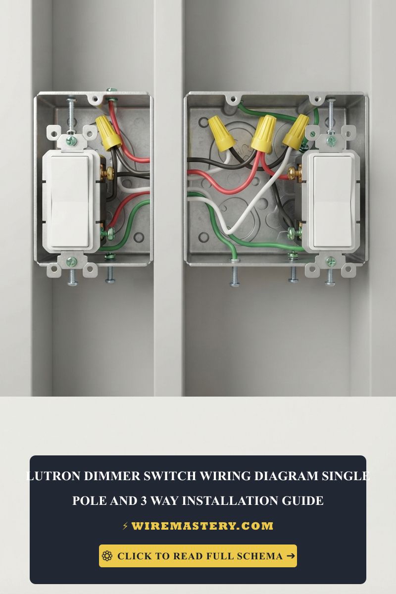
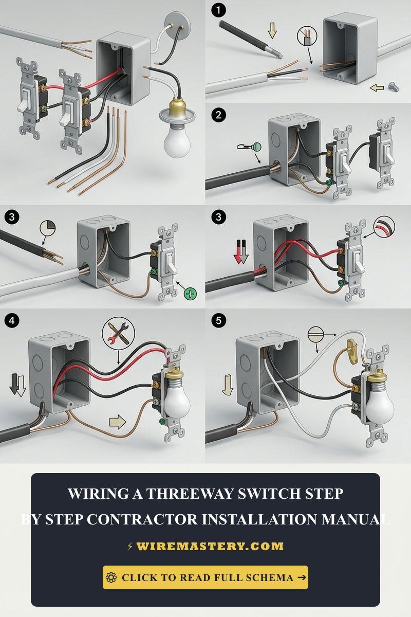
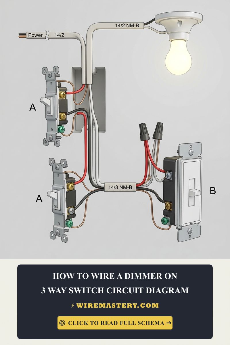
- Common terminal: A conventional 3-way mechanical switch has one common terminal, often identified by a darker screw. Depending on its location in the circuit, the common is associated with the supply or the switched connection to the light. The terminal’s appearance does not identify which house conductor is attached to it.
- Traveler pair: The two traveler terminals connect the two control locations. They are often associated with conductors in the same cable, but insulation color is not reliable proof of a conductor’s function in an existing or modified installation.
- Dimmer leads and terminals: A dimmer may use screw terminals or attached leads. Labels, colors, and supported circuit arrangements vary by product; follow the diagram supplied for the exact model.
Common 3-Way Terminal Markings
These are general functions, not instructions for connecting house wires. Markings and lead colors vary by switch and dimmer model.
| Terminal or lead marking | General circuit role | Important limitation |
|---|---|---|
| Common / COM (often a darker screw on a mechanical switch) | The common connection is associated with the supply or the switched path to the light, depending on its location in the circuit. | The marking does not tell you which house conductor is attached or whether it is line or load. |
| Traveler terminals (often a pair of brass screws on a mechanical switch) | Connect the two control locations in a conventional 3-way arrangement. | Terminal and lead colors vary; do not identify conductors by insulation color alone. |
| Ground (green screw or lead) | Protective equipment-grounding connection, installed as specified by the device instructions. | It is not a neutral or a normal current-return path. |
| Neutral (when required, often marked N or neutral) | Supplies a neutral connection for dimmers designed to use one. | Not every dimmer requires it, and a white-looking wire is not proof that a conductor is a neutral. |
The supply and the light’s load are not guaranteed to be in a particular wall box. A generic diagram that assumes which box contains the line or load may not match the house wiring.
Product and Compatibility Checklist
| What to check | Why it matters |
|---|---|
| Control at the second location | Some dimmers work with a standard 3-way switch; others require a specific companion. Confirm the permitted combination in the exact model’s instructions. |
| Dimming from both locations | Some arrangements provide dimming at one location and on/off control at the other. Multi-location dimming may require a designated companion device. Features vary by model. |
| Bulb or fixture type | LEDs and integrated LED fixtures need to be compatible with the dimmer. Check the manufacturer’s compatibility list using the exact bulb or fixture model. |
| Load and device rating | Confirm the dimmer’s supported lamp types, load range, and ratings against the lighting being controlled. Do not assume a dimmer suitable for one load is suitable for another. |
| Neutral requirement | Some dimmers need a neutral connection; others do not. Requirements depend on the device and circuit. Never use the equipment grounding conductor as a neutral. |
| Physical fit and box capacity | Smart dimmers can have a different size and wiring arrangement from a mechanical switch. Have an electrician check the box and installation if fit or capacity is uncertain. |
Do not choose a dimmer solely by brand, product photo, or wire colors. Find the full model number and check its current installation guide before purchase. The documentation should state whether the device supports your control arrangement, lamp type, and neutral requirements.
CRITICAL ELECTRICAL SAFETY: Neutral is not ground. Some dimmers, including some smart models, require a neutral connection; others are designed for installations without one. Check the instructions for the exact model. Never use a bare or green equipment grounding conductor as a substitute for neutral. A white-looking wire or the absence of a visible white wire does not, by itself, confirm the circuit’s wiring or product compatibility. Do not open the box to investigate; ask a qualified electrician if the requirement is unclear. NEC Article 250 addresses grounding and bonding; it is not a blanket rule that every dimmer requires a neutral.
Technical Materials & Diagnostic Testing Checklist
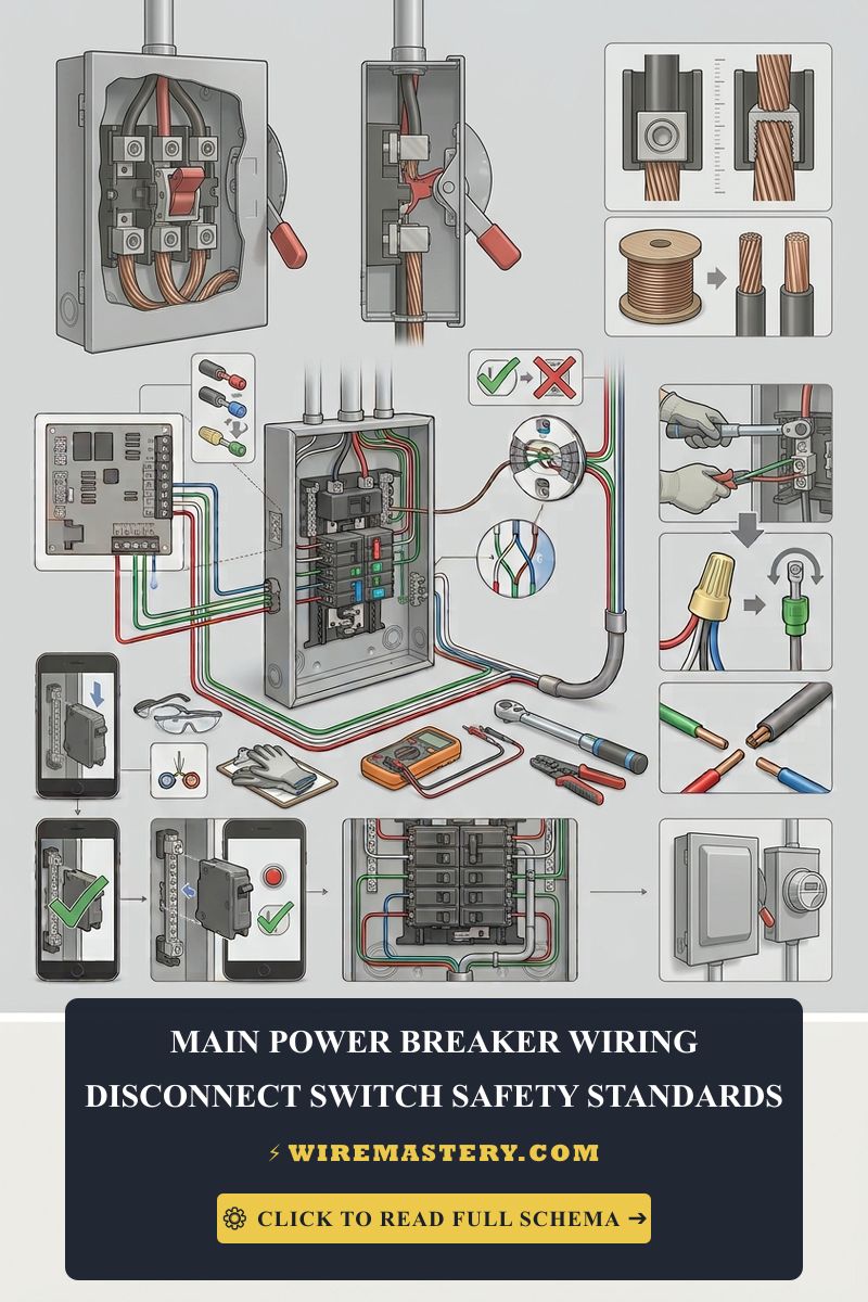
The following are examples of tools a qualified electrician may use. Owning them does not make it safe to open an energized switch box. A non-contact voltage detector is only a preliminary indicator and cannot, by itself, confirm that conductors are de-energized. Do not use these tools to probe or alter household wiring yourself.
| Electrical Tool | Professional Use | Safety Limitation |
|---|---|---|
| Non-contact voltage detector | Preliminary screening for the possible presence of AC voltage. | A negative indication does not prove that a conductor is safe to touch. It does not replace verification with an appropriately rated tester. |
| Digital multimeter | Electrical measurements and troubleshooting by a qualified person using an instrument rated for the circuit. | Testing can involve exposed live parts; this guide does not provide live-measurement instructions. |
| Wire strippers | Preparing conductors to the size and strip length specified by the device manufacturer. | Use only after the circuit has been safely isolated and verified by a qualified person. |
| Listed wire connectors | Joining compatible conductors when the connector is rated for their material, size, and number. | A connector’s listing does not confirm that a particular wiring arrangement is correct. |
Installation and Wire Identification
The manufacturer’s diagram for the exact dimmer and circuit type must determine the connections. Terminal labels and lead colors vary, and house conductors may not follow the expected arrangement. Do not use another model’s diagram or identify a conductor by color alone.
This article does not explain how to expose, test, or move conductors. In particular, do not energize a switch box with devices pulled out to identify a live common wire. Working inside a switch box can expose hazardous voltage. If the existing wiring does not clearly match the dimmer manufacturer’s diagram, leave the wiring in place and contact a licensed electrician.
Local code and permit requirements depend on the jurisdiction and the adopted code edition. A qualified local electrician can check the circuit, grounding, box capacity, and applicable requirements. A general online article or a broad code reference cannot confirm that an installation meets local rules.
Troubleshooting Common Dimmer Symptoms
- The light dims at only one location: This may be the intended behavior of the selected dimmer and companion arrangement. Check the exact product’s description before treating it as a fault. If the controls do not behave as documented, contact the manufacturer or an electrician.
- The light flickers or has a limited dimming range: Possible causes include an incompatible lamp, an unsupported load, a product setting, or an installation issue. Check the exact bulb or fixture against the dimmer’s compatibility list; the symptom alone does not identify a wiring fault.
- LED bulbs glow faintly when switched off: Some dimmer and LED combinations may show residual light, but this does not establish a specific cause. Check the product’s troubleshooting guide. Do not add a load capacitor or change connections unless the exact manufacturer’s instructions specify it.
- The breaker trips, the control becomes unusually hot, or there is buzzing or a burning smell: Stop using the control and contact a qualified electrician. Do not repeatedly reset a tripping breaker or open the switch box to investigate.
When requesting help, note the dimmer and lamp model numbers, which control locations are affected, and when the symptom occurs. You can gather those details from product labels or packaging without removing the switch or touching conductors.
Safety and Manufacturer Guidance
Electrical switches, grounding, and box capacity are subject to applicable electrical codes, but code requirements and adoption vary by location. Follow the product’s installation instructions and local requirements; use a qualified electrician when the circuit or the correct product is uncertain.
For product-specific diagrams and troubleshooting, use the official Lutron support site or Leviton support site and search by the exact model number. Those instructions apply to the manufacturer’s own products and should not be transferred to a different model or brand without confirmation.
Choosing a compatible 3-way dimmer starts with confirming the desired control behavior, the lamp type, and the exact product requirements. Common and traveler terminals help explain how a 3-way circuit is organized, but they are not enough to identify house conductors or determine a safe connection. When the manufacturer diagram does not clearly match the existing setup, have a licensed electrician complete the assessment and installation.