How to Wire a Leviton GFCI Outlet: Step-by-Step NEC Guide
Wiring a Leviton GFCI (Ground Fault Circuit Interrupter) outlet is a foundational electrical safety project for any residential property. Required by the National Electrical Code (NEC) in moisture-prone zones such as kitchens, bathrooms, laundry rooms, and outdoor spaces, a GFCI receptacle monitors current balance to prevent severe shock hazards.
This technical guide provides a step-by-step installation walkthrough, precise code diagrams, and hardware troubleshooting parameters tailored for standard United States branch circuits.
Understanding Line vs. Load Terminals on Leviton GFCIs
The most common installation failure when handling a Leviton GFCI outlet wiring loop is misidentifying the incoming power source. Unlike standard duplex receptacles, a GFCI device features two distinct electrical zones:
- LINE Terminals: This is where the incoming hot and neutral wires from your main breaker panel connect. This terminal pair supplies continuous 24V/120V power directly to the internal smart monitoring chips of the device.
- LOAD Terminals: Hidden behind a yellow warning tape from the factory, these terminals send downstream GFCI protection to other standard outlets further down the branch circuit.
⚠️ NEC Code Compliance Warning: If you hook up your main incoming power wires to the LOAD terminals by mistake, the outlet’s indicator light might turn on, but it will not provide any power to the front face plugs, and the safety trip mechanism will fail completely. Always verify your source lines before mounting the hardware.
Standard Residential Wire Gauge and Amperage Selection
Before stripping your conductors, verify your circuit rating matches your choice of Leviton hardware and wiring dimensions:
| Circuit Amperage | Correct Wire Gauge (AWG) | Romex Sheath Color (US) | Leviton Device Face |
|---|---|---|---|
| 15 Amps | 14 AWG Solid Copper | White | Standard T-Slot absent |
| 20 Amps | 12 AWG Solid Copper | Yellow | T-Slot present on face |
Technical Materials and Tools Checklist
Executing a clean, code-compliant install requires specific trade tools: an insulated Phillips and flathead screwdriver set, wire strippers, an electrical box (plastic or grounded metal gang box), and a trusted digital voltage tester.
Step-by-Step Installation Manual
1. Circuit Isolation and Voltage Verification
Locate your property’s main service panel. Disengage the specific circuit breaker switch feeding the work area. Lock out or tag the breaker box to ensure no one toggles it back on. Prior to loosening any screws, insert your non-contact voltage tester directly into both slots of the old receptacle to confirm the branch is completely de-energized.
2. Stripping and Preparing Conductor Leads
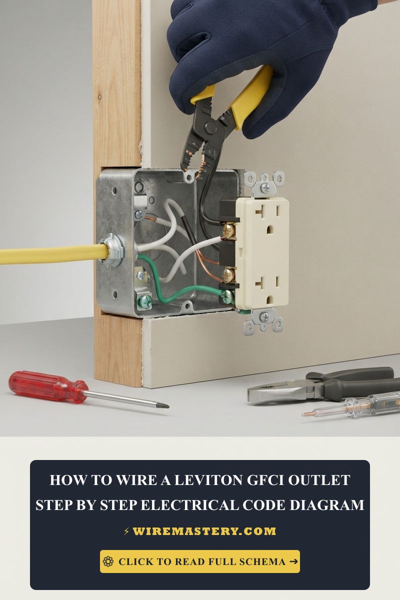
Carefully extract the wiring bundle from the wall enclosure box. As shown in technical wiring mockups, use your wire strippers to remove exactly 3/4 inch of outer insulation from your 12 AWG or 14 AWG solid copper lines. Inspect the bare metal for deep nicks or scoring; if damaged, cut the conductor back and re-strip a clean section.
3. Terminating the Connections to the Leviton Base
Look closely at the back markings on your Leviton device to trace the LINE terminal block:
- Connect the LINE Hot: Insert the Black wire into the rear pressure clamp or wrap it clockwise around the brass screw terminal labeled LINE. Tighten securely.
- Connect the LINE Neutral: Insert the White wire into the terminal clamp or wrap it clockwise around the silver screw labeled LINE.
- Establish Equipment Grounding: Connect your Bare copper or solid green wire to the hex-shaped green grounding screw located at the bottom framework of the device.
Note for Metal Box Installations: If you are mounting your hardware into a metal gang box (like the structural frame illustrated above), you must use a short green grounding pigtail wire to bond both the metal box casing and the Leviton device framework to the main ground line.
4. Torque and Structural Placement
Tighten all termination screws to the manufacturer’s recommended torque specifications to prevent loose connection arcing over time. Wrap the sides of the device with two layers of high-quality electrical tape to insulate the exposed side terminals. Gently fold the solid copper wires in an alternating accordion pattern back into the box cavity, ensuring the green ground line does not contact the hot or neutral brass side screws.
Post-Installation Commissioning and Testing
- Re-engage the main breaker switch at your electrical panel. The Leviton status LED indicator should illuminate green or remain blank depending on the specific smart model series.
- Press the RESET button completely into the faceplate until you hear a sharp mechanical click.
- Plug an external circuit tester or lamp into the socket to verify power delivery.
- Press the TEST button. The RESET pad should instantly pop forward, shutting off power to the lamp immediately. This mechanical lockout confirms your ground fault protection module is working perfectly.
NEC Compliance & Official Safety Standards
Adhering to strict electrical codes saves lives. The NEC mandates that all GFCI installations maintain continuous grounding pathways, proper box volume fills (to prevent heat accumulation inside walls), and tamper-resistant (TR) faces in residential living zones to shield children from structural shock hazards.
For current NFPA 70 guidance on GFCI protection, LINE and LOAD connections, grounding, and receptacle replacement, consult the Official NFPA 70: National Electrical Code (NEC).
Conclusion
Installing a Leviton GFCI receptacle depends on correctly identifying the LINE and LOAD terminals, matching the device to the branch-circuit rating, and completing the TEST/RESET check after wiring. De-energize and verify the circuit before handling the conductors, follow the manufacturer’s terminal instructions, and stop for qualified help if the device will not reset or test correctly.







