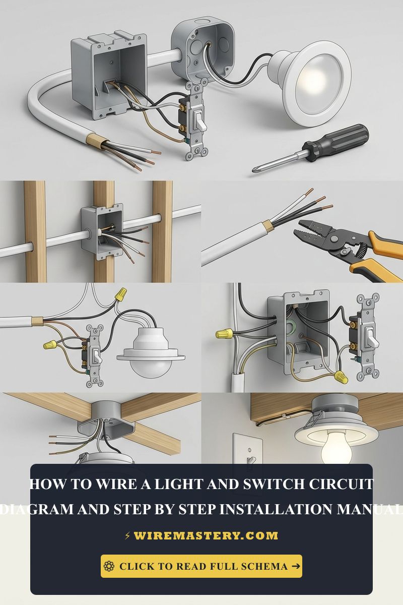
How to Wire a Light and Switch: Switch Loop Topology
Engineering a code-compliant residential lighting network requires an advanced understanding of branch circuit topologies, current-carrying path geometries, and electromagnetic field cancellations. In standard electrical rough-ins, line voltage traditionally routes from the primary distribution panel board straight into the local wall switch box before extending upward to feed the luminaire housing yoke. However, spatial architectural constraints often demand deploying a specialized Switch Loop Topology. In this configuration, the source line voltage bypasses the wall switches entirely, routing directly into the ceiling junction box box first. This layout creates a complex diagnostic tracking pattern where a single multi-conductor cable drops down to the wall switch box, carrying both the constant ungrounded line hot and the switched hot return leg within the same bundle sleeve.
This technical manual outlines the physical mechanics of traditional and ceiling-fed switch loops, dual-point traveler distributions, and personal protective equipment (PPE) requirements.
Core Switch Loop Engineering Thresholds
Before pulling multi-conductor sheaths through structural ceiling joists or terminating side screws, verify these criteria:
- The Inductive Heating Mitigation Rule: Alternating current (AC) passing through a single conductor generates a fluctuating magnetic field. To prevent this field from inducing severe eddy currents that heat up metallic conduits or framing staples, the constant line hot and the switched hot return line must occupy the exact same cable jacket or raceway, canceling out opposing magnetic vectors.
- The Re-Identification Mandate: Under NEC Article 200.7(C), if a white wire within an NM-B Romex cable is deployed to carry ungrounded line voltage (such as dropping power down a switch loop), its insulation tip must be permanently re-identified using black or red electrical tape at every accessible splice termination.
- The Voltage Potential Window: Standard residential single-pole toggle interfaces operate on a single-phase nominal 120V AC loop, demanding clean copper mechanical contacts to prevent carbon arcing under reactive ballast loads.
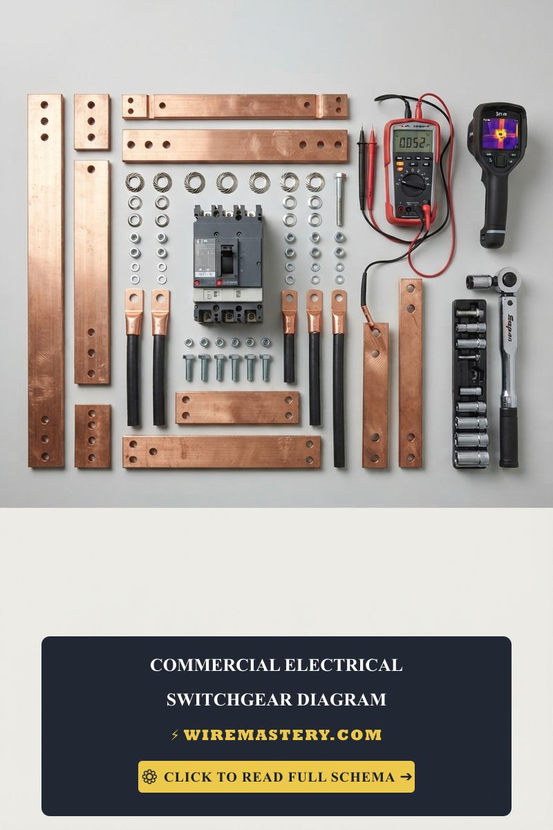
Technical Materials & Low-Impedance Splicing Toolkit
Safely opening high-density ceiling enclosures and auditing multi-point traveler lines requires specific insulated field tools and testing instrumentation:
| Electrical Installation Tool | Primary Engineering Purpose & Trade Safety Threshold |
|---|---|
| True RMS Digital Multimeter | Category CAT III 600V certified to accurately map hot lines from floating legs. |
| Non-Contact AC Voltage Tester | High-sensitivity sensor to confirm absolute circuit de-energization inside deep boxes. |
| Ergonomic Solid Wire Strippers | Calibrated to strip #14 AWG and #12 AWG solid copper wire insulation clean without nicking. |
| High-Leverage Linesman Pliers | Hardened cutting jaws to execute code-compliant, tight mechanical pigtail pre-twists. |
| UL-Listed Insulated Wire Nuts | Rated for specific maximum combination fills to sustain constant spring clamping forces. |
Sizing Conductor Cross-Sections & Breaker Ampacities (NEC 310.16)
Selecting an incorrect conductor profile introduces dangerous electrical resistance, leading to progressive insulation decay inside wall cavities. The National Electrical Code strictly regulates branch circuit conductor cross-sections based on nominal overcurrent protection limits. Apply those conductor-sizing rules to the switch-loop layout described here.
- 14 AWG Solid Copper Conductor (White Romex Jacket): Sized exclusively for 15-Amp overcurrent breakers. The universal configuration deployed for standard residential branch lighting grids.
- 12 AWG Solid Copper Conductor (Yellow Romex Jacket): Sized exclusively for 20-Amp overcurrent breakers. Mandatory if your lighting circuit ties into a shared small appliance branch loop or high-density commercial layout.
Decoding the Ceiling-Fed Switch Loop Matrix
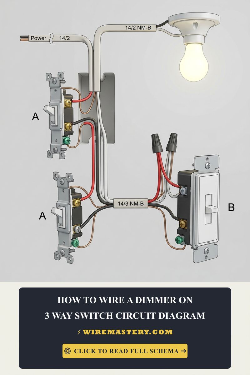
To read a how to wire a light and switch circuit diagram with complete clarity, you must ignore generic assumptions and trace functions by matching wire re-identifications to their specific loop directions:
Standard Single-Device Switch Loop Wire Mapping
| Conductor Core Position | Factory Insulation Color | Field Re-Identification Wrapping | Circuit Technical Role & Direction |
|---|---|---|---|
| The Supply Drop Line | White Conductor Core | Wrapped with Black/Red Tape | Drops un-switched 120V power from ceiling box down to the wall switch terminal. |
| The Switch Return Leg | Black Conductor Core | Kept Original Black | Routes toggled 120V power from the switch back up to the luminaire hot terminal. |
| The Equipment Ground | Bare Copper Core | Kept Raw / Green Sleeve | Sacrificial safety return path bonded to all metallic box enclosures. |
Step-by-Step Installation Blueprint: Wiring a Ceiling-Fed Switch Loop
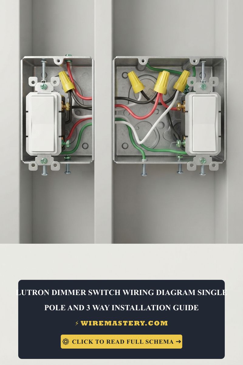
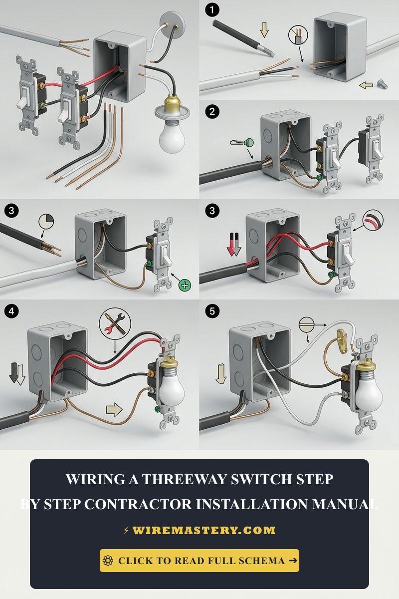
To configure a professional, code-compliant switch loop topology where the primary power source enters the ceiling luminaire box first, apply the systematic field installation sequence detailed in the technical documentation.
Summary of Installation Steps
- Pre-Installation Isolation Protocol: Disengage the dedicated circuit breaker and verify a complete 0V AC state using a non-contact voltage tester. Ensure proper wire gauges are used (14 AWG for 15-amp or 12 AWG for 20-amp circuits).
- Conductor Re-Identification (NEC 200.7(C)): Re-identify white conductors acting as hot feed lines by wrapping them with black or red electrical tape at both terminal ends.
- Ceiling Luminaire Junction Box: Connect the incoming panel hot to the re-identified white switch wire, the incoming panel neutral to the fixture’s white wire, and the switched return black wire to the fixture’s black hot lead.
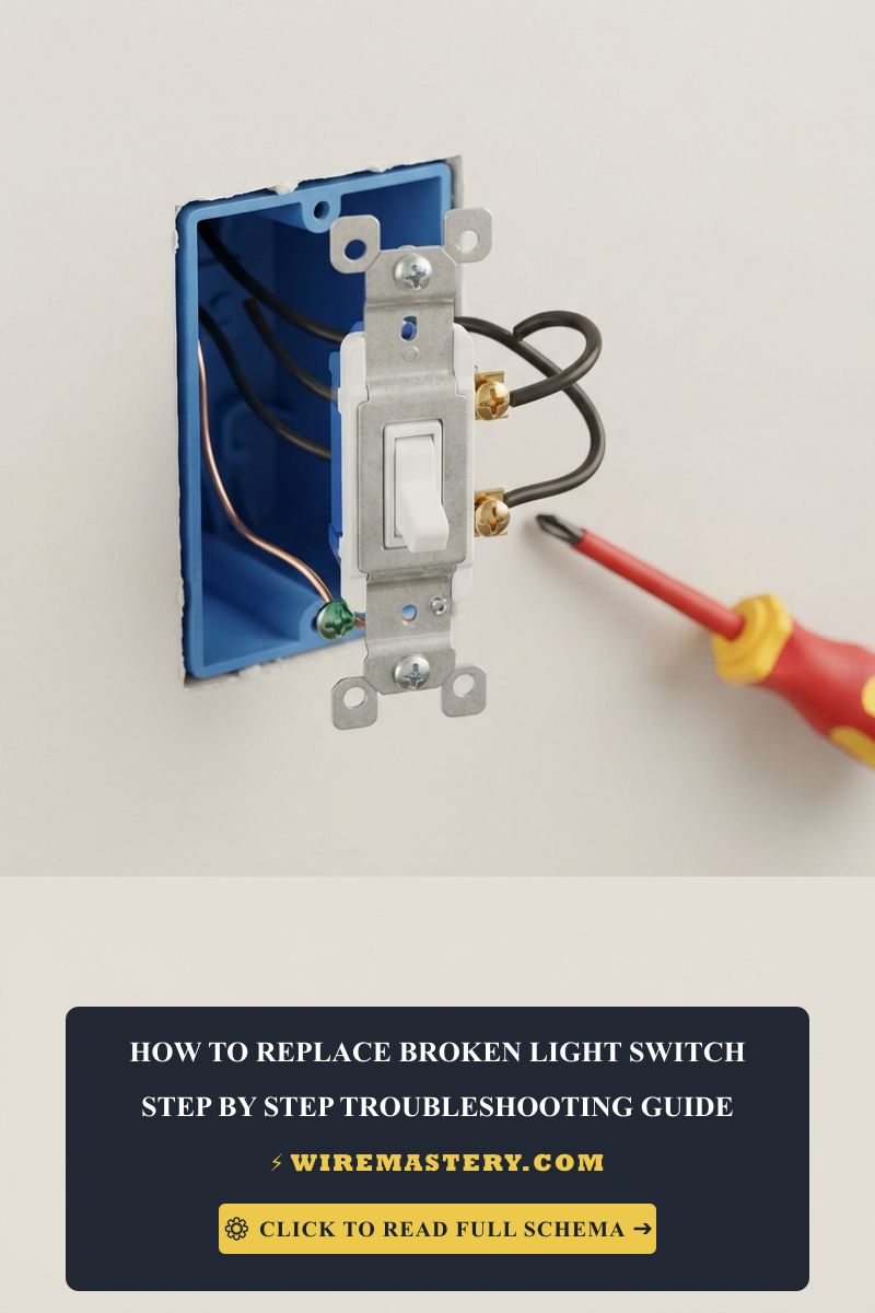
- Standalone Wall Switch Box: Secure the continuous hot and switched hot return wires to the appropriate single-pole switch terminals and attach the bare copper ground to the green grounding screw.
For complete, unabridged step-by-step instructions, safety protocols, and wiring diagrams, please refer to the referenced technical manual.
Troubleshooting Common Switch Loop Failures
- The Circuit Breaker Trips Instantly: Indicates a dead short circuit fault, typically from exposed copper touching the box or incorrect neutral/hot bridging.
- The Light Bulb Stays ON Continuously: Caused by a parallel path override where the panel hot bypasses the switch and connects directly to the fixture.
- The Wall Switch Plate Feels Warm: Symptom of high-resistance or loose terminal connections under continuous operation.
National Electrical Code Structural Integrity Standards
Adhering to residential switch loops and junction box guidelines under NEC Article 404 (Switches) and Article 314 ensures full safety compliance. For detailed technical definitions and updated national regulations, consult the Official NFPA 70: National Electrical Code (NEC).
Conclusion
This article explains ceiling-fed switch loop topologies and executing pristine conductor re-identifications ensures safe, lighting grids.