Nest Thermostat Installation: Calibrating Wall Draft Seals
Executing a professional, Nest smart thermostat installation requires looking past low-voltage wiring hookups and addressing the thermodynamic micro-environments surrounding the wall-mounted base plate assembly. A common yet overlooked failure mode in smart climate controls is localized temperature sensor calibration drift caused by internal wall cavity convection currents, professionally known as the wall draft effect. When an installer drills into drywall sheets to route low-voltage Class 2 thermostat conductors, they open a physical pathway into uninsulated structural cavities. This void acts as a chimney, channeling drafts that bias the thermostat’s internal thermistors, causing short-cycling or delayed HVAC responses. For setups driving advanced home systems, integrating these thermal isolation standards alongside a verified no-neutral smart switch installation loop safeguards overall automated efficiency.
This reference manual outlines the physics of structural thermal drift, the precise calculations for spatial mounting heights, and field diagnostic toolkits to ensure absolute calibration integrity.
Core Thermal Calibration Parameters
Before drilling pilot holes or landing 18 AWG solid copper conductor lines onto terminal blocks, verify these structural criteria:
- The 5-Foot Wall Mounting Rule: To capture a true representation of ambient room temperature zones, a thermostat must be mounted physically between 5 feet (60 inches) and 5.5 feet (66 inches) above the finished floor level. This elevation avoids the cold air pools concentrated at floor boundaries and the intense heat layers trapped near ceiling framing tracks.
- The Convection Draft Vector: If the structural wire penetration hole behind the Nest base plate is left unsealed, negative air pressure inside the wall cavities will draw unconditioned air directly across the rear logic board sensor vents, distorting room readings by up to 5°F to 8°F.
- The Radiant Shield Buffer: Smart thermostats incorporate active Wi-Fi transceivers that generate localized internal hardware heat. The device relies on continuous ambient air convection across its outer casing vents to dissipate this energy; seating the hardware tight against deep recessed accent pockets chokes this boundary layer.
Technical Materials & HVAC Thermal Auditing Toolkit
Safely routing control cable lines, measuring microscopic wall drafts, and calibrating infrared temperature zones requires specific diagnostic instrumentation and field tools:
| HVAC Calibration Tool | Primary Engineering Purpose & Safety Threshold |
|---|---|
| Infrared Laser Thermometer | Measures absolute, non-contact wall and ambient room surface temperatures to isolate thermal sags. |
| Acoustic / Thermal Anemometer | High-precision meter used to measure microscopic feet-per-minute (FPM) air drafts exiting wire holes. |
| Plenum-Rated Expanding Foam / Putty | High-dielectric fire-retardant compound used to seal raw cable wall penetrations permanently. |
| Torpedo Cross-Check Level | Ensures the Nest mercury-free solid-state sensor orientation aligns square to the drywall grid. |
| Precision Strippers & Nut Drivers | Calibrated to prepare solid copper 18 AWG wiring loops without scoring the metal cores. |
Sizing Low-Voltage Signaling Lines & Structural Wire Controls (NEC 725.179)
When routing a fresh thermostat line through vertical wall framing tracks, standard high-voltage building code metrics are completely irrelevant. Instead, technicians deploy specialized control cables matching NEC Class 2 power limitations:
- 18 AWG Solid Copper Conductor (The System Benchmark): Standard multi-conductor wire harness profile (e.g., 18/5 or 18/8 wire lines). It limits internal resistance parameters while maintaining a rigid profile to snap into spring-loaded terminal clips.
- The Insulation Temperature Rating Limit (NEC 725.179): Thermostat cable jackets running through interior wall paths must carry a minimum safety classification code of CL2 or CL2R (Riser), incorporating fire-retardant PVC wraps rated to withstand up to 60°C (140°F) minimum without degrading under adjacent structural heat stresses.
Technical Phase 1: Isizing Wall Draft Vectors and Base Plate Seals
To systematically eliminate temperature reading errors during a Nest upgrade, a professional field engineer applies this advanced wall cavity isolation protocol:
1. Power Isolation and Structural Disassembly
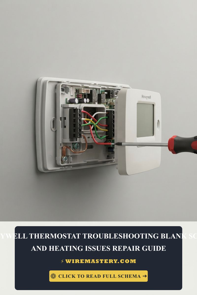
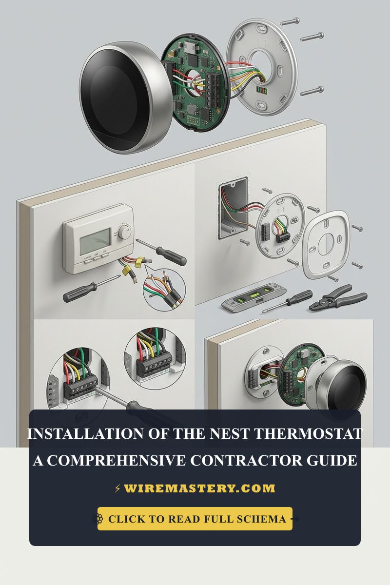
Navigate to the primary distribution panel center and toggle the circuit breaker supplying power to the furnace or air handler cabinet to the absolute “OFF” position. Verify a true 0V AC state on the wire tracks using your multi-tester. Back out the mounting ears of the legacy thermostat and remove the wall plate.
2. Auditing and Sealing the Wire Penetration Junction
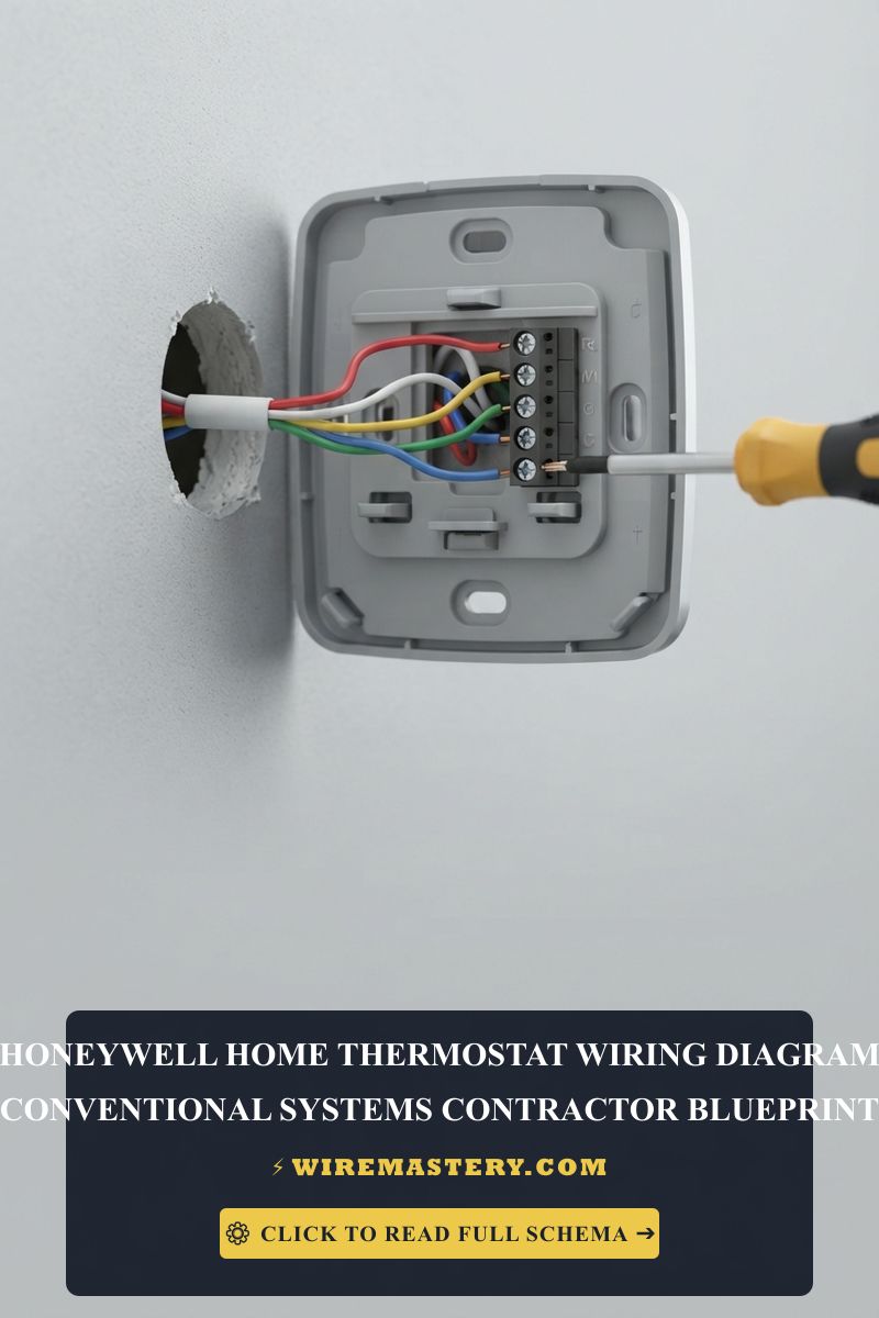
- Pull the 18 AWG solid copper wire bundle forward out of the wall. Inspect the raw hole punched into the sheetrock panel behind the wire track.
- Take your thermal anemometer and monitor the opening. You will typically register an active draft moving through the void due to stack-effect pressure variances inside the building envelope.
- Executing the Code-Compliant Seal (NEC 300.21): Take a block of non-hardening electrical insulation duct sealing putty or a bead of plenum-rated low-expansion foam. Stuff the compound directly into the raw drywall opening surrounding the 18 AWG cable sheath. Pack the putty tightly to seal the air gap completely. This physical block forces all internal wall drafts to remain trapped behind the drywall veneer, preventing unconditioned air from ever contacting the rear sensor nodes of your new Nest.
Technical Phase 2: Structural Backplate Mounting and Software Offset Calibration
Once the wall cavity draft vector has been physically blocked with insulation putty, you must execute the final mechanical alignment and baseline software synchronization sequence:
1. Mounting the Mechanical Trim Plate Assembly
- Take the optional premium Nest trim plate (the plastic decorative backplate designed to cover scars from older, bulkier thermostats). Position it square against the drywall over your sealed wire penetration gap.
- Pass the 18 AWG solid copper wire bundle clean through the center aperture hole of the Nest base plate unit.
- Place your torpedo cross-check level across the top edge of the base plate. Center the bubble fluid perfectly to ensure the internal solid-state accelerometer and mercury-free orientation sensors align square to the room’s gravity vectors.
- Drive the mounting drywall screws directly into your wall anchors using your insulated screwdrivers. Torque them down until the base plate sits flat against the sheetrock without bowing the plastic housing.
2. Terminating Conductor Leads and Seating the Display
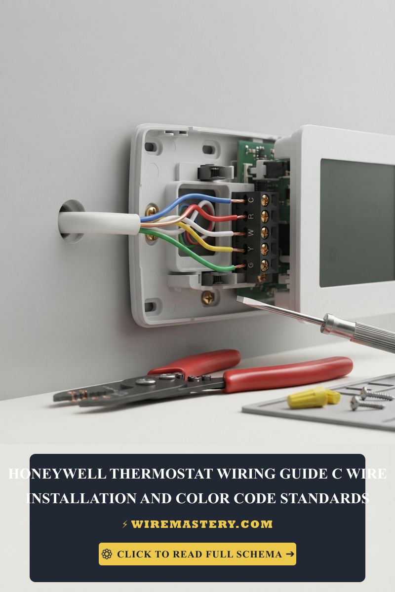
- Strip exactly 3/8 inch of insulation off your solid copper wire cores using your precision wire strippers. Ensure the exposed copper shanks are completely straight and free of deep metal scores.
- Depress the integrated terminal push-tabs on the Nest base plate and insert the conductors into their assigned ports matching their layout designations: R (or Rc) to R, W1 to W1, Y1 to Y1, G to G, and C to C. Release the tabs to allow the internal spring clamps to lock onto the copper.
- Push the wire loops flat into the rear channel gutter space so they do not protrude outward. Align the main circular liquid-crystal display faceplate with the base pins and press inward firmly until you hear a mechanical click, locking the hardware matrix together. Re-engage the panel breaker.
🛠️ Systemic Short-Cycling Alert: Look closely at the air distribution tracks and register orientations showcased across our residential HVAC design manuals. Notice that a smart thermostat must never be mounted physically in direct line-of-sight of an active heating or cooling supply register duct vent. Placing the Nest where conditioned air blows directly onto its casing creates an artificial local thermal feedback loop, causing the system to short-cycle aggressively (turning on and off every few minutes), which overloads breaker contact blocks and accelerates compressor component wear.
Troubleshooting Common Nest Thermal & Power Anomalies
- The Nest Displays an Inaccurate Room Temperature (Too High): This occurs due to radiant heat absorption or an unshielded Wi-Fi chip power spike. Verify that the thermostat is not mounted onto an exterior wall that absorbs intense afternoon sunlight, or adjacent to a kitchen oven appliance track. If structural placement cannot be altered, navigate to the Nest hardware settings menu window, access Advanced Thermal Calibration, and program a manual Temperature Offset Value (e.g., -2°F or -3°F) to mathematically align the display readout with a verified laboratory thermometer baseline.
- The HVAC System Shuts Off Before Reaching the Target Temperature: An absolute symptom of internal wall convection leaking. If your expanding foam or duct sealing putty setup failed to fully seal the raw sheetrock hole, air currents will bypass the block under heavy blower cycles. The negative pressure draws cold or hot air from the attic straight into the Nest’s rear sensor chamber, tricking the microprocessor logic boards into turning off the heating/cooling calls prematurely. Re-extract the base plate and pack the putty cavity tighter.
- The Display Registers a “Delayed” Status Message: Indicates severe voltage starvation or current restriction on the 24V AC signaling loop. This happens when an installation forces the Nest to operate without a true Common (C) wire return track, relying on its internal power-stealing algorithm. During extended heating/cooling cycles, the battery drains completely, forcing the unit to drop its Wi-Fi card and display delay messages while it struggles to recover voltage. Install a true C-wire adapter loop or an external isolation transformer immediately to stabilize the line potential.
National Construction Codes & Spatial Integrity Standards
Adhering to strict national installation codes protects your smart home infrastructure, maintains property valuation, and ensures full property insurance compliance. The National Electrical Code strictly regulates low-voltage signaling control cables, wiring methods, and wall penetrations under NEC Article 300 (Wiring Methods) and Article 725:
- Spread of Fire Mandates (NEC 300.21): Electrical installations inside hollow walls, floors, and ceiling cavities must be made so that the structural openings around cables do not substantially increase the possible spread of fire or products of combustion. Sealing the thermostat wire penetration hole with an approved fire-retardant duct sealing putty fulfills this safety mandate perfectly.
- Class 2 Circuit Isolation Boundaries (NEC 725.136): Low-voltage thermostat control cable lines are strictly prohibited from entering conduits, raceways, or junction boxes housing high-voltage 120V/240V building branch loops unless isolated by approved metallic dividers, protecting smart solid-state processors from line voltage leaks.
For the NFPA 70 provisions relevant to this guide on Nest Thermostat Installation: Calibrating Wall Draft Seals, consult the Official NFPA 70: National Electrical Code (NEC).
Conclusion
This article explains Google Nest thermal convection dynamics, sealing raw sheetrock wire penetrations to eliminate wall cavity draft vectors in full compliance with NEC Article 300.21, and adjusting software temperature offset calibration parameters transforms smart home optimization into a highly controlled science. By keeping mounting elevations strictly within standard spatial height windows, preventing short-cycling HVAC feedback loops, and respecting mandatory NEC Class 2 low-voltage separation boundaries, you construct an exceptionally resilient residential technology framework. For final checks, complete panel breaker power isolation safety checkups before handling control wires, utilize certified non-contact infrared instruments, and complete every low-voltage calibration step with systematic precision.