Nest Thermostat Troubleshooting: Fixing E73, E74 & N260 Power Errors
Executing a reliable, long-term technical repair on an advanced Google Nest smart thermostat network experiencing systemic hardware lockouts demands a structured diagnostic roadmap that bridges low-voltage semiconductor logic with mechanical HVAC safety loop constraints. Unlike legacy bimetallic mercury wall plates, the Nest Learning Thermostat platform functions as a highly complex microprocessor-driven communication node. It relies on continuous monitoring of its internal lithium-ion power cells and alternating current (AC) signal impedance levels. When a Nest screen goes blank or flashes a critical overcurrent warning, the root failure is almost never a software glitch; it is an active physical indicator of a tripped condensate float switch, a blown transformer fuse, or a high-resistance wiring degradation fault inside the property’s climate infrastructure.
This technical manual outlines the precise mechanical and electrical definitions behind Nest power error codes E73, E74, and N260, alongside advanced laboratory voltage isolation diagnostics.
Core Nest Electrical Infrastructure Metrics
Before decoupling terminal clips on the Nest base plate or testing air handler control terminals, memorize these low-voltage criteria:
- The Nominal Operational Voltage: Nest hardware platforms require a stable, continuous source voltage floating strictly between 22V AC and 30V AC delivered across the C (Common) wire and the R (Rc/Rh) lines.
- The Lithium Battery Amperage Threshold: The internal backup battery cells inside the Nest display faceplate sustain their charge by drawing a low-current parasitically from the HVAC control lines. To stay online during long system standby windows, the device demands an open-circuit current parameter reading of at least 20 mA to 40 mA continuous.
- The Electronic Bridging Logic: Nest thermostats do not incorporate mechanical jumpers. Instead, internal solid-state micro-relays automatically map and bridge power pathways between Rc (Cooling Power) and Rh (Heating Power) based on active conductor insertion patterns.
Technical Materials & Nest Advanced Diagnostic Instrumentation
Safely tracing micro-ampere current leaks and measuring physical low-voltage AC sags requires specific electronics testing equipment and insulated hand tools:
| HVAC Diagnostic Tool | Primary Engineering Purpose & Safety Threshold |
|---|---|
| True RMS Digital Multimeter | Category CAT III 600V certified to accurately check 24V AC lines and loop resistances. |
| Non-Contact Low-Voltage Tester | High-sensitivity instrumentation calibrated to detect fields down to 12V AC. |
| Insulated HVAC Terminal Jumpers | Fused alligator-clip wire leads to safely bypass field switches during isolating tests. |
| Precision Wire Strippers & Cutters | Calibrated to cleanly remove outer PVC casings off thin 18 AWG solid copper conductors. |
| Dielectric Contact Cleaner Solvent | Fast-evaporating compound to purge carbon scaling and oxidation off wall plate pin blocks. |
Sizing Control Line Gauge Overgrowths (NEC Article 725)
To maintain absolute data integrity and prevent high-resistance power sags that trigger unexpected Nest power-cycling loops during peak seasonal operations, your control wires must align with NEC Class 2 power limitations:
- 18 AWG Solid Copper Conductor (The System Benchmark): Standard field diameter for multi-conductor thermostat wires. It limits structural resistance factors over extensive path lengths.
- The Distance Attenuation Limit: If your low-voltage cable run extends past 125 feet from the central furnace cabinet to the living room faceplate, standard 18 AWG wire resistance drops current loops. You must upsize the infrastructure run to a #16 AWG solid copper line to prevent the Nest from triggering false N260 power starvation messages.
Decoding the Primary Nest Power Error Codes
When a Nest system experiences electrical current drops, it reports the breakdown utilizing explicit alphanumeric codes on its display faceplate. Technicians must understand the specific circuit architecture targeted by each code:
🚨 Error Code E73: No Power to Rc Wire Detected
This diagnostic code confirms the Nest has completely lost its 24V AC positive link on the cooling power terminal line.
- The Failure Mode: It is almost always caused by a tripped HVAC Condensate Float Switch. When an air conditioner’s primary drain line clogs with algae sludge, condensation water backs up into the overflow pan. The mechanical float switch rises, opening the contact loop and instantly slicing the 24V AC line running down the Rc wire to protect the property from structural water damage.
🚨 Error Code E74: No Power to Rh Wire Detected
This diagnostic code confirms the Nest has completely lost its 24V AC positive link on the heating power terminal line.
- The Failure Mode: This indicates a breakdown on the furnace or boiler side. Common causes include a tripped integrated thermal limit switch inside the furnace heat exchanger (due to choked airflow from a clogged air filter) or a blown 3-Amp blade fuse on the primary integrated control board.
🚨 Error Code N260: Missing Common Wire Starvation Warning
This code displays when the Nest is wired without a dedicated C (Common) wire and its power-stealing algorithm can no longer cycle fast enough to charge the internal lithium cells. The thermostat enters a volatile power-save loop, dropping off the Wi-Fi network repeatedly.
Technical Phase: Conducting a Live Nest Base Plate Voltmeter Audit
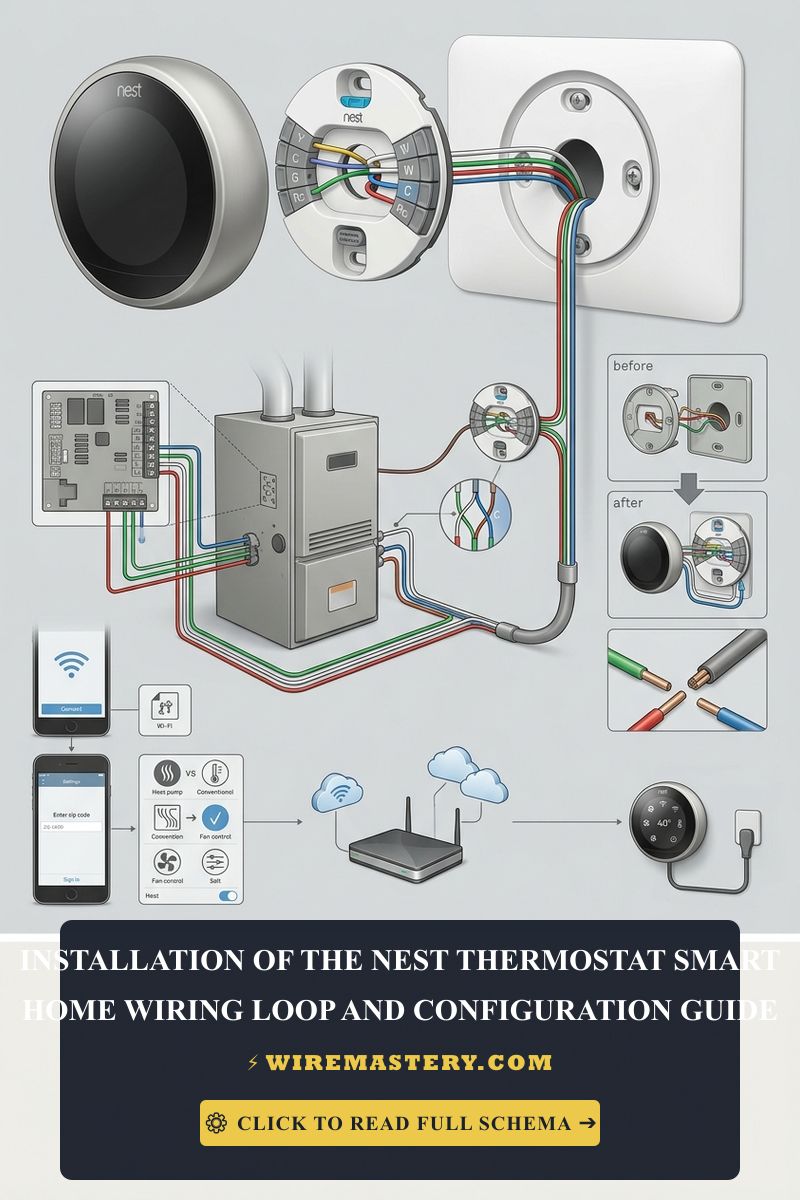
When your Nest display throws an E73 or E74 error code, never replace the expensive hardware unit before executing a structured low-voltage voltage matrix audit at the wall base plate connector pins using your digital multimeter:
The 24V AC Voltage Mapping Sequence
- Put on your Class 00 insulated work gloves and ANSI-rated safety glasses. Pull the Nest display unit straight forward off the wall base plate to expose the raw terminal push-tabs.
- Rotate your digital multimeter dial to the AC Voltage setting (V AC).
- Execute the Multitester Pin Readings Matrix:
- Test Rc to C: Place your red probe onto the Rc terminal tab and your black probe onto the C terminal tab.
- A Healthy Circuit Loop: The meter must display a stable reading between 22V AC and 28V AC. If it reads a flat 0V AC, the primary line has experienced a break or a safety float switch lockout upstream.
- Test Rh to C: Move your red probe to the Rh terminal tab while keeping the black probe anchored on the C wire.
- A Healthy Circuit Loop: The meter must display approximately 24V AC. A reading of 0V AC confirms a blown furnace board fuse or an open high-temperature limit switch.
- Test Rc to Rh (Isolation Check): Place your red probe on Rc and the black probe on Rh.
- The System Parameters: The multitester should display 0V AC under normal single-transformer configurations because both lines originate from the same low-voltage tap. If it reads 24V AC, you are dealing with a dual-transformer system (separate furnace and AC power), and you must ensure the internal bridging logic is not shorting the systems together.
- Test Rc to C: Place your red probe onto the Rc terminal tab and your black probe onto the C terminal tab.
🛠️ Float Switch Overriding Note: Look closely at the low-voltage HVAC layout schematics showcased throughout our master troubleshooting manuals. Notice that a condensate overflow switch is wired in series with the Rc conductor line. If you encounter an emergency E73 lockout during an operational audit, you can temporarily clamp a fused jumper wire across the float switch terminal blocks to bypass the sensor loop. If the Nest immediately powers back on, you have verified the electrical infrastructure is flawless, and the root problem is a clogged HVAC drain manifold that must be cleared chemically.
Step-by-Step Field Manual: Resolving Clogged HVAC Condensate Pan Lockouts
1. Hard Power Isolation Protocol
Prior to working inside any HVAC air handler or handling drain lines, navigate to your property’s main service distribution box and toggle the circuit breaker feeding the furnace/blower system to the absolute “OFF” position. Verify a true 0V AC state on the main terminal strip before handling internal components.
2. Purging and Clearing the Condensate Drain Line
If a tripped float switch is cutting power to your Rc wire, causing an intense E73 error loop:
- Locate the PVC drain pipe line coming from the cooling evaporator coil basin enclosure. Find the secondary inline float switch housing assembly.
- Unpack the mechanical float switch module head. If the internal plastic cylinder is floating in dirty water, the primary drain is blocked.
- Attach your high-capacity wet/dry shop vacuum hose tightly to the exterior exit mouth of the PVC drain line outside the property envelope. Wrap a microfiber cloth around the connection to achieve a tight mechanical vacuum seal.
- Engage the vacuum cleaner for a continuous 2 to 3 minutes. The intense suction will pull out accumulated algae slabs, dust mounds, and rust sediment that are blocking the line, draining the overflow pan instantly.
- Pour a cup of biodegradable HVAC pan cleaner down the line to dissolve residual scale. Re-seat the float switch head, re-engage the panel breaker, and watch the Nest display clear the E73 code automatically.
Troubleshooting Common Nest Power Fluctuation Faults
- The Nest Battery Voltages Float Below 3.6V DC (The N260 Loop): This behavior indicates severe voltage starvation due to a missing true Common (C) wire return path. Access the hidden technical menu window on the Nest display screen and audit the “Power” metrics parameters. If the battery parameter reads below 3.6V DC, or if
lincurrent drops below 20 mA, the Nest cannot stay connected to the Wi-Fi card. You must install a true C-wire adapter loop or pull a new 18/5 solid copper conductor line to protect the internal battery lifespan. - The Heating or Cooling Stays On Continuously (Stuck Relays): This indicate a dead short circuit or a failed solid-state triac relay inside the Nest backplate base. If a technician accidentally shorts the R and W lines together with a metal screwdriver while the unit is live, the high-amperage surge will weld the internal semiconductor switching gates shut. Replace the Nest base plate assembly immediately.
- The Thermostat Displays a Pulsing Green LED Light: This symptom occurs when the internal micro-chips are downloading an automated firmware upgrade or recovering from an extended power outage. If the green light pulses continuously for over 15 minutes while the screen remains black, the processor is locked in a boot-loop sandbox due to low input voltage. Pull the faceplate off the wall yoke and charge the unit manually via its rear micro-USB or USB-C port using a standard phone charging block for 1 hour to stabilize its memory registers.
National Electrical Code Class 2 Low-Voltage Safety Enforcements
Adhering to strict national installation codes protects your home automation systems from damage and ensures full property insurance compliance. The National Electrical Code strictly regulates remote-control, signaling, and power-limited circuits under NEC Article 725 (Class 1, Class 2, and Class 3 Remote-Control, Signaling, and Power-Limited Circuits). Use those low-voltage circuit rules when troubleshooting the Nest thermostat faults covered here.
- Class 2 Short-Circuit Protective Headroom (NEC 725.121): Low-voltage Nest thermostat automation loops are constitutionally classified as Class 2 signal lines. The code mandates that these systems must be supplied by a current-limited transformer that cannot deliver more than 100 VA (Volt-Amperes) overall. This limitation ensures that even if a mouse chews through an 18 AWG thermostat wire inside a hidden wall cavity, the short circuit cannot generate enough thermal energy to ignite structural timber or insulation materials.
- Separation from Power Branches (NEC 725.136): Thermostat cable sheaths are strictly prohibited from passing through the same conduits, raceways, or junction boxes housing high-voltage 120V/240V main building branches unless isolated by approved metallic dividers, ensuring raw line voltage can never leak into sensitive solid-state low-voltage smart displays.
For the NFPA 70 provisions relevant to this guide on Nest Thermostat Troubleshooting: Fixing E73, E74 & N260 Power Errors, consult the Official NFPA 70: National Electrical Code (NEC).
Conclusion
This article explains Google Nest advanced power error codes, executing live Rc/Rh terminal audits using CAT III certified multi-testers, and clearing clogged HVAC condensate pan blockages with heavy-duty wet/dry vacuum extraction systems transforms chaotic smart home troubleshooting into a highly controlled science. By keeping control line fluctuations within strict 24V AC code tolerances, realigning loose wire loom terminal blocks on base plates, and respecting mandatory NEC Class 2 circuit isolation boundaries inside equipment racks, you build an exceptionally resilient, safe home grid environment. For final checks, complete HVAC service de-energization checks before handling raw lines, utilize certified diagnostic instruments, and complete every low-voltage maintenance phase with systematic precision.