Miniature Circuit Breakers: Residential Working Principles
Engineering a resilient residential electrical distribution framework requires an advanced operational understanding of overcurrent protection metallurgy, magnetic trip physics, and panel-board bus bar integration standards. Often classified globally as miniature circuit breakers (MCBs) or residential thermal-magnetic circuit breakers, these mechanical switching components serve as the critical line of defense inside a property’s service panel center. Their dual-action engineering automatically isolates downstream branch conductors the sub-second a hazardous thermal overload or high-amperage dead short circuit develops. However, integrating these components demands strict alignment with geographical manufacturing frameworks; substituting European IEC-rated trip curves inside a standard North American UL 489 distribution board violates federal inspection guidelines. For setups driving precision automated hardware, cross-referencing your panel expansion with clean no-neutral smart switch installation guidelines prevents progressive inductive chattering from wearing out internal breaker contacts.
This reference manual outlines the thermodynamic mechanics of bimetallic bending, the high-speed physics of magnetic solenoids, and step-by-step panel load balancing workflows.
Core Overcurrent Protection Parameters
Before snapping a new circuit breaker assembly onto an energized panel bus bar or handling conductor terminations, decode these foundational parameters:
- The Continuous Loading Buffer: Under structural safety guidelines, a residential circuit breaker must not be loaded past 80% of its total nominal ampacity rating under sustained continuous loads (running for 3 hours or more). For a standard 20-Amp breaker, peak continuous load must drop below 16 Amps.
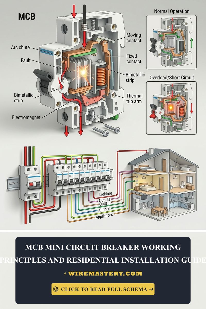
- The Arc Chute Splitting Matrix: When breaker contact points separate during an active high-amperage short circuit, the current attempts to sustain itself by ionizing the air, creating a blinding plasma arc exceeding 5000°F. Breakers incorporate an integrated arc chute—a series of parallel metal plates that split, cool, and mechanically extinguish the plasma envelope within milliseconds.
- The AIC Headroom Rating: Every residential breaker carries an Ampere Interrupting Capacity (AIC) rating (typically 10,000 AIC for standard homes). This parameter dictates the maximum fault-current the mechanical frame can safely interrupt without experiencing catastrophic structural housing detonation.
Technical Materials & Service Panel Commissioning Toolkit
Safely backing out deadfront panels and securing high-amperage terminal wire screws requires specialized 1000V-rated insulated tools and precise diagnostic instrumentation:
| Electrical Panel Tool | Primary Engineering Purpose & Safety Threshold |
|---|---|
| True RMS Digital Clamp Meter | Category CAT III 600V minimum to audit live conductor current draws without breaking loops. |
| Calibrated Dial Torque Wrench | Mandatory trade tool to torque breaker lug screws down to exact inch-pound specifications. |
| Dual-Phase Non-Contact Tester | Audibly monitors internal bus bars to verify complete panel energy isolation. |
| 1000V Insulated Screwdriver Set | Square-drive (Robertson) insulated tips to prevent lateral slips against live tabs. |
| Insulated Panel Puller Pliers | High-dielectric pliers engineered to seat or extract stubborn plug-on neutral breakers cleanly. |
Sizing Conductor Cross-Sections & Breaker Ampacities (NEC 310.16)
Matching an oversized circuit breaker to thin copper lines is a leading cause of catastrophic structural residential fires. The National Electrical Code enforces strict conductor diameter minimums based on the breaker’s overcurrent trip threshold:
- 15-Amp Circuit Breaker: Must be paired exclusively with a minimum of #14 AWG solid copper conductors (standard white Romex jacket). Reserved for general residential lighting loops and bedroom outlets.
- 20-Amp Circuit Breaker: Must be paired exclusively with a minimum of #12 AWG solid copper conductors (standard yellow Romex jacket). Mandatory for kitchen small appliance branch circuits (SABC) and bathroom plugs.
- 30-Amp Circuit Breaker: Must be paired exclusively with a minimum of #10 AWG solid copper conductors (standard orange Romex jacket). Required for heavy localized continuous loads like electric water heaters and clothes dryers.
The Dual-Action Operation Matrix: Thermal vs. Magnetic Trip Mechanics
To pass a field audit, you must separate overcurrent faults into two distinct kinetic behaviors executing inside the breaker housing mold:
1. The Thermal Deflection Loop (Inverse-Time Overload Protection)
The thermal trip mechanism handles sustained low-level overcurrent events, such as plugging two space heaters into a single 15A bedroom circuit.
- The Physics: Current passes directly through an internal, precision-welded bimetallic strip made of two dissimilar metals with contrasting thermal expansion rates.
- The Kinetic Action: As the current exceeds the breaker rating, the metal strip heats up and begins to warp or bend laterally. The greater the current over-growth, the faster the metal deflects (inverse-time characteristics). Once the strip reaches its physical deflection threshold, it releases the mechanical trip latch, snapping the spring-loaded contacts open to isolate the branch.
2. The Electromagnetic Solenoid Plunge (Instantaneous Short-Circuit Protection)
The magnetic trip mechanism handles high-amperage dead short circuits and ground faults.
- The Physics: The conductor loop winds around a small internal electromagnetic coil (solenoid) surrounding a spring-loaded steel core plunger.
- The Kinetic Action: Under normal loads, the magnetic field is too weak to compress the internal spring. However, the instant a dead short circuit bypasses circuit resistance, amperage current surges to thousands of Amps. The magnetic field instantly amplifies, sucking the plunger forward with immense mechanical force to hit the trip armature. This process isolates the short circuit in less than 1/60th of a second (under one full AC cycle), stopping wire vaporization before a structural fire can ignite.
🛠️ Bus Bar Compressive Seating Note: Look closely at the split-phase distribution panel layouts showcased across our master electrical installation portfolios. Notice that a standard plug-on circuit breaker relies on mechanical jaw compression to clamp onto the live copper or tin-plated aluminum panel bus bar. When snapping a new breaker into place, always verify the jaw clips seat completely flat. A loose, half-seated breaker clip creates an active micro-air gap that induces severe voltage arcing, generating localized heat that will pit the bus bar and melt the rear plastic casing of your new breaker long before it can trip.
Step-by-Step Service Panel Board Breaker Installation
Upgrading or adding an overcurrent breaker inside a main distribution panel demands total concentration and rigid structural safety habits. Follow this field sequence to complete the deployment safely:
1. Primary Service Energy Isolation
Go to the top of your master panel enclosure box. Locate the primary Main Disconnect Circuit Breaker (typically a massive 150A or 200A multi-pole switch) and toggle it to the full “OFF” position. Place your padlock lockout clamp over the handle framing to block accidental re-activation.
2. Live Bus Bar Voltmeter Verification
Remove the outer metal deadfront cover panel screws carefully. Take your digital multimeter, set it to AC Voltage mode (V AC), and place your black probe onto the master neutral bus bar. Touch your red probe to the individual branch bus bars one by one to confirm an absolute 0V AC state across the entire workspace area before handling any components.
3. Physical Mounting and Conductor Termination
- Strip exactly 1/2 inch of insulation off your clean #12 AWG or #14 AWG solid copper wire core using your precision wire strippers.
- Insert the raw copper tip deep into the breaker’s terminal lug pressure plate slot. Use your calibrated torque wrench to tighten the terminal screw down to the exact manufacturer torque spec stamped on the side of the breaker housing (typically 35 to 45 inch-pounds). Loose terminations are the number one cause of melted panel gutters.
- Hook the rear plastic mounting foot of the breaker onto the panel’s outer plastic retaining rail. Pivot the breaker inward toward the center bus bar, and press down firmly using your insulated panel puller pliers until the internal jaw clips snap flat and lock onto the live bus bar tab.
- Route the white neutral wire and bare copper ground line straight to their respective grounding bus bars, neatening the wire bundle paths into clean 45° angles along the panel casing borders. Re-mount the deadfront plate, remove your padlock, and re-engage main utility power.
Troubleshooting Common Circuit Breaker Anomalies
- The Breaker Tripps Instantly the Second You Flip It ON: This behavior indicates an active dead short circuit or a hard ground fault downstream. You have a hot wire making direct metal-to-metal contact with a neutral conductor or the grounded steel gang box. Do not attempt to force the breaker handle closed. Use your digital multimeter in unpowered continuity mode to isolate and locate the short circuit inside your wall boxes before re-energizing the branch line.
- The Breaker Handles Standard Loads but Hums Loudly Under Peak Load: This indicates a high-resistance contact point or mechanical loose play inside the internal magnetic armature assembly. Alternating current at 60 Hz creates a micro-vibration field; if the internal core springs lose tension over decades of service, the plates will chatter, generating an audible hum. Replace the breaker unit immediately to mitigate localized thermal damage.
- An Overload Breaker Refuses to Reset or Stay Latched: When a breaker trips due to a thermal overload, the internal bimetallic strip remains extremely hot and physically bent. If you attempt to reset it instantly, the mechanical latch will fail to catch. You must wait a minimum of 2 to 3 minutes for the metallurgy to cool down and straighten back to its baseline stance before flipping the toggle hard to “OFF” to reset the internal springs, then hard back to “ON”.
National Electrical Code Breaker & Panel Regulations
Adhering to strict national installation codes protects your home investment, maintains property valuation, and ensures full insurance compliance. The National Electrical Code strictly regulates overcurrent protections, panel spaces, and worker boundaries under NEC Article 240 (Overcurrent Protection) and Article 408 (Switchboards and Panelboards):
- Circuit Directory Identification Mandates (NEC 408.4): Every circuit breaker inside a residential distribution panel must be legibly and clearly identified as to its specific purpose on a permanent circuit directory attached to the panel door faceplate. Utilizing vague labels like “Outlets” or leaving slots blank violates federal inspection guidelines.
- Circuit Breaker Location Boundaries (NEC 240.24): Overcurrent protection devices must be easily accessible and installed so that the center of the grip handle, when at its highest position, does not extend past 6 feet, 7 inches (2.0 meters) above the finished floor level, ensuring swift manual disconnect safety access during an emergency infrastructure crisis.
For the NFPA 70 provisions relevant to this guide on Miniature Circuit Breakers: Residential Working Principles, consult the Official NFPA 70: National Electrical Code (NEC).
Conclusion
This article explains circuit breaker thermal-magnetic trip curves, calculating proper 80% continuous branch loading limitations, and executing precise panel terminations using calibrated torque wrenches transforms complex service expansions into safe, electrical operations. By eliminating European IEC curve mismatches, keeping raw copper conductor terminals free of loose pressure plate play, and enforcing strict NEC Article 240 space height regulations, you construct an unshakeable, resilient home grid environment. For final checks, complete main switch power de-energization checks, deploy insulated square-drive screwdrivers, and execute every terminal step with safety-first care.







