What is an MCB? Working Principles, MCCB vs. MCP Guide
Understanding the internal engineering design and operational thresholds of a Miniature Circuit Breaker (MCB) is a mandatory requirement for layout planning code-compliant residential grids, industrial automated control lines, and off-grid solar arrays. As a primary overcurrent protection device, an MCB provides a resettable safety barrier that safeguards branch circuit conductors against progressive thermal overloads and instantaneous short circuits. Unlike sacrificial single-use fuses, modern miniature breakers combine mechanical longevity with sub-second trip acceleration, making them the standard hardware standard for low-voltage residential networks.
This manual demystifies the thermal-magnetic working principles of MCBs, the physical engineering differences separating MCCBs and MCPs, and precise wire-gauge ampacity sizing matrices in strict alignment with the National Electrical Code (NEC).
Core Circuit Breaker Parameters
Before snapping an overcurrent device onto a distribution bus bar or DIN rail layout, decode these foundational parameters:
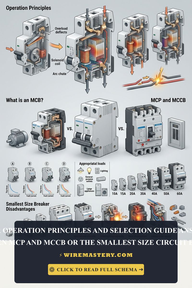
- The Dual-Trip Matrix: MCBs deploy two independent internal trip mechanisms: a bimetallic strip that warps under long-duration overload heat, and an electromagnetic solenoid that pulls a trip lever instantly during high-amperage dead shorts.
- Short-Circuit Breaking Capacity: Stamped on the device casing (typically 10,000 AIC or 10kA for residential units). This metric defines the maximum fault current the breaker can safely extinguish without physical housing destruction.
- Continuous Load Derating Factors: Under NEC guidelines, a standard miniature breaker must never handle a continuous load (running for 3 hours or more) exceeding 80% of its total nominal rating unless explicitly listed as a 100%-rated device.
Technical Materials & Diagnostic Testing Checklist
Safely executing breaker installations and tracing terminal resistance faults requires specific trade equipment and insulated hand tools:
| Panel Installation Tool | Primary Technical Purpose |
|---|---|
| Calibrated Torque Wrench | Absolute code requirement to tighten breaker box lug screws to exact manufacturer inch-pound values. |
| Insulation Resistance Tester | Measures megohm isolation margins across conductor jackets before energizing the bus bar. |
| 1000V Insulated Screwdrivers | Cushion-grip drivers certified under ASTM F1505 standards to prevent accidental contact arcs. |
| Digital Auto-Ranging Multimeter | Measures clean AC/DC voltage drops across terminal blocks and audits continuity paths. |
| Non-Contact AC Voltage Tester | Audibly confirms that service enclosure internal bus bars are fully de-energized. |
Official Conductor Sizing & Ampacity Matrix (NEC Table 310.16)
Bypassing correct wire thickness ratios causes high-resistance heat accumulation inside wall cavities, resulting in premature insulation decay. The National Electrical Code strictly dictates overcurrent protection limits based on copper wire diameter parameters; utilizing an undersized conductor violates federal fire codes:
| MCB Nominal Current Rating | Minimum Copper Conductor Sizing (AWG) | Standard Romex Jacket Color (US) | Primary Branch Application Context |
|---|---|---|---|
| 15 Amps | #14 AWG Solid Copper | White | Low-draw lighting loops, bedroom outlets, and smoke detectors. |
| 20 Amps | #12 AWG Solid Copper | Yellow | Kitchen small appliances, bathroom plugs, and laundry nodes. |
| 30 Amps | #10 AWG Solid Copper | Orange | Central AC condenser lines, clothes dryers, and pool pump loops. |
| 40 Amps | #8 AWG Stranded Copper | Black | Heavy-duty dual-phase electric ranges and cooktop nodes. |
| 50 & 60 Amps | #6 AWG Stranded Copper | Black | Main distribution lines feeding secondary 120V/240V subpanels. |
Mechanical Physics: How Does an MCB Operate?
To accurately troubleshoot a tripping branch, an engineer must isolate whether the device is responding to a progressive thermal anomaly or a catastrophic magnetic fault:
1. The Thermal Overload Mechanism (Delayed Action)
When multiple downstream appliances push current draw slightly past the nominal breaker limit (e.g., drawing 23 Amps on a 20A breaker), an internal bimetallic strip made of two bonded metals with differing thermal expansion coefficients begins to warp. As heat builds progressively over minutes, the mechanical deflection reaches a calculated physical threshold that releases the latch mechanism, dropping the toggle to the “TRIPPED” position to protect wire jackets from overheating.
2. The Magnetic Short-Circuit Solenoid (Sub-Millisecond Acceleration)
When a high-voltage hot wire directly touches a neutral or ground line, the current spikes instantaneously to thousands of Amperes. This extreme rush of current passes through an internal solenoid coil, generating a massive magnetic field. The resulting kinetic force drives a plunger directly into the primary trip lever, opening the contact terminals within less than 10 milliseconds to quench the destructive fault arc before it triggers a structural explosion.
Industrial Classifications: MCB vs. MCCB vs. MCP Guide
Selecting the appropriate overcurrent device requires understanding the operational differences separating residential miniature units from high-capacity industrial hardware. Utilizing an incorrect classification violates installation safety standards and risks system destruction under heavy industrial loads.
Core Device Category Breakdowns
- Miniature Circuit Breakers (MCB): Engineered for low-voltage, low-current environments. They feature non-adjustable, fixed thermal-magnetic trip curves calibrated to safeguard standard branch circuits.
- Molded Case Circuit Breakers (MCCB): Designed for heavy commercial and industrial distribution networks. They handle massive current loads, incorporate advanced short-circuit interrupting cells, and feature fully adjustable trip settings.
- Motor Circuit Protectors (MCP): Specialized protection devices engineered strictly for electric motor circuits. Unlike standard breakers, they feature instantaneous magnetic protection only, relying on independent thermal overload relays to shield motor windings from phase failures or locked-rotor conditions.
Comprehensive Circuit Protection Device Matrix
| Technical Feature | Miniature Circuit Breaker (MCB) | Molded Case Circuit Breaker (MCCB) | Motor Circuit Protector (MCP) |
|---|---|---|---|
| Primary Application | Residential & Light Commercial | Industrial & Master Distribution | Dedicated Electric Motor Loops |
| Nominal Current Range | 0.5A to 125 Amps | 15A to 2,500 Amps | 1A to 630 Amps (Typical) |
| Trip Curve Calibration | Fixed / Non-Adjustable | Fully Adjustable Trip Settings | Adjustable Magnetic Sensitivity |
| Breaking Capacity (AIC) | 4.5kA to 25kA Maximum | 10kA to 200kA Maximum | High-Interrupting Industrial Limits |
| Mounting Architecture | Standard 35mm DIN Rail / Plug-In | Heavy-Duty Bolt-On Frame | Modular DIN Rail / System Block |
Understanding Instantaneous Tripping Characteristics (Curves B, C, & D)
An MCB’s performance is further classified by its instantaneous magnetic trip curve, which defines how much surge current the breaker can handle before tripping immediately. Matching these curves to your load profile prevents severe nuisance tripping during device startup cycles.
- Type B Curves (Residential Standard): Trips instantaneously when current reaches 3 to 5 times the nominal rating. Designed to shield resistive loads like home incandescent lighting networks, bedroom plugs, and electronic entertainment circuits.
- Type C Curves (Commercial Baseline): Trips instantly at 5 to 10 times the nominal rating. Ideal for inductive loads with moderate initial inrush currents, such as standard fluorescent office lighting, local workshop machinery, and residential garage vacuum loops.
- Type D Curves (Heavy Inductive Target): Trips exclusively at 10 to 20 times the nominal rating. Calibrated to withstand severe transient startup surges from industrial transformers, commercial X-ray equipment, and large centralized multi-phase electric motor pumps.
🛠️ Panel Safety Analysis Note: Look closely at the industrial model designs displayed throughout your guide assets. Notice how miniature circuit breakers must seat perfectly square on the distribution bus bars or DIN rail channels. If a breaker body is loose, or if the metal contact jaw inside is bent, it will create a high-resistance localized hotspot that will melt the surrounding plastic enclosure under a continuous 20-amp load long before the safety breaker can trip.
Disadvantages & Engineering Limitations of Smallest-Sized Breakers
While ultra-low amperage miniature breakers (such as 0.5A to 5A MCBs) provide exceptional precision for isolating delicate instrumentation loops, deploying the smallest size circuit breakers carries distinct engineering challenges:
- Massive Susceptibility to Nuisance Tripping: Small thermal-magnetic trip curves are highly sensitive. Transient startup inrush spikes from small switching power supplies can cause the magnetic solenoid to trip the circuit immediately, even when no true short circuit exists.
- High Internal Resistance (Voltage Drop): Because ultra-small breakers require thin bimetallic elements and high-turn solenoid coils to register low currents, they exhibit significantly higher internal resistance than standard 20A breakers. This resistance can induce noticeable voltage drops across long signal lines.
- Thermal Ambient Derating Sensitivity: Small breakers are highly vulnerable to ambient room temperature changes inside crowded panel enclosures. If surrounded by hot high-voltage lines, the bimetallic element will warp early, tripping the load below its true nominal rating.
NEC Compliance & Overcurrent Protection Standards
Adhering to strict construction codes ensures your home infrastructure remains legal, fully insurable, and structurally safe. The National Electrical Code strictly regulates general overcurrent device selections under NEC Article 240 (Overcurrent Protection):
- Conductor Protection Rules (NEC 240.4): Conductors must be protected against overcurrent in accordance with their rated ampacity thresholds. You must ensure your circuit breaker setting never exceeds the thermal capacity of your downstream wire gauge under any structural circumstance.
- Standard Ampacities (NEC 240.6): This article defines the standard ampere ratings for fuses and inverse time circuit breakers, providing the structural boundary parameters required to complete formal home load calculations.
For the NFPA 70 provisions relevant to this guide on What is an MCB? Working Principles, MCCB vs. MCP Guide, consult the Official NFPA 70: National Electrical Code (NEC).
Conclusion
This article explains miniature circuit breaker operation principles and selection workflows transforms complex residential retrofits into safe, electrical installations. By tracking the difference between thermal overloads and magnetic short circuits, matching B/C/D trip curves to your exact load applications, and avoiding code-violating wire gauge mismatches, you construct a professional-grade home grid. For final checks, complete panel deadfront power testing, utilize certified diagnostic instruments, and complete every terminal step with safety-first precision.