Radiant Floor Heating Installation Guide: Residential Thermal Engineering
Integrating an electric radiant floor heating system beneath a premium residential hardwood, tile, or engineered laminate floor layout demands a precise alignment with thermal resistance physics, branch circuit ampacity scaling, and strict multi-layer subfloor insulation benchmarks. Professionally classified as electric zone space-heating matrices, these systems utilize high-resistance embedded alloy wire elements to transform electrical current into uniform radiant infrared energy, warming the floor veneer from the subfloor up. However, executing these layouts requires extreme engineering care; because these resistance cables are permanently embedded beneath thin-set mortar or wooden sleeper tracks, a single mechanical wire nick or an under-sized branch conductor will drop the loop offline, requiring destructive floor demolition to resolve the fault. For properties driven by smart climate grids, ensuring your floor sensors tie into verified low-voltage C-wire transformer configurations safeguards digital automated thermostats against systemic current sags.
This technical blueprint outlines the mathematical equations for calculating heating wattages, the physical deployment of non-inductive resistance meshes, and advanced laboratory pre-installation testing toolkit matrices.
Core Radiant Infrastructure Parameters
Before rolling out resistance heating spools or embedding layout matrices into self-leveling underlayments, establish these structural criteria:
- The Wattage Density Benchmark: Residential electric radiant floor networks are engineered to deliver a thermal density floating between 10 Watts and 15 Watts per square foot depending on localized climate zones and the structural thermal resistance (R-value) of the finished floor backing.
- The Non-Cut Resistance Constraint: Electric heating cables operate as closed, continuous resistance loops calibrated to an exact physical length at the factory. Cutting, shortening, or splicing the core resistance heating wire to fit a smaller room is strictly prohibited; altering the wire length collapses its total internal resistance, causing current draw to spike catastrophically and melting the PVC insulation wrap within minutes.
- The Continuous Load Classification: Under structural safety definitions, electric space-heating equipment operates for sustained windows exceeding 3 hours under winter loads, requiring all supplying breakers and feeder paths to scale up to 125% headroom capacities.
Technical Materials & Radiant Heating Commissioning Toolkit Checklist
Safely auditing insulation boundary layers and verifying resistance wire matrices before mortar embedment demands specific laboratory-grade instruments and non-conductive tools:
| Radiant Testing Instrument | Primary Engineering Purpose & Trade Application |
|---|---|
| Digital Storage Megohmmeter | A specialized high-voltage tester (“Megger”) used to verify wire insulation integrity at 500V to 1000V DC. |
| True RMS Digital Multimeter | Category CAT III 600V certified to accurately check baseline coil resistances and sensor drops. |
| Digital Auto-Ranging Monitor | A small clip-on alarm box that continuously monitors wire continuity during mortar pours. |
| High-Density Plastic Floating Trowel | Used to spread self-leveling mortar compounds smoothly without scraping underlying cables. |
| Infrared Laser Thermometer | Maps active thermal footprints across the finished floor faceplate to isolate heating balances. |
Conductor Profiles & Load Calculations (NEC Article 424)
Sizing branch circuits for heavy electric heating mats demands absolute adherence to copper cross-sections to eliminate progressive thermal wire decay behind drywall sheets. The National Electrical Code strictly regulates fixed electric space-heating equipment under NEC Article 424 boundaries:
- 120V AC General Single-Mat Loops: Permissible only for small, localized spatial upgrades (such as single guest bathrooms under 100 sq. ft.). A typical 1,200-Watt mat draws 10 Amps continuous, demanding a dedicated 20-Amp breaker equipped with #12 AWG solid copper conductors wrapped inside a yellow Romex jacket.
- 240V AC Whole-House Multi-Mat Layers: The industrial contractor standard for large living rooms and open-concept floor framing. Operating on a dual-phase 240V circuit cuts active current draws in half relative to wattage, allowing installers to power up to 300 square feet of heating mats over a single 30-Amp double-pole breaker utilizing #10 AWG stranded copper THHN lines enclosed within a yellow or orange jacket profile.
Technical Phase 1: The Three-Stage Ohmic Diagnostics Matrix
The single most critical failure mode during electric floor heating installation is wire insulation structural breach caused by sharp trowel edges or worker footsteps during the concrete or hardwood subfloor assembly. Contractors execute a strict three-stage resistance testing sequence using a digital multimeter and megohmmeter to catch faults before the floor is sealed:
Test Stage A: Core Conductor Resistance Checking
- Rotate your digital multitester dial to the Resistance mode (Ohms Ω).
- Place your testing probes onto the two primary current-carrying lead wires (typically Black and Red, or Black and White) extending out from the heating mat cold-lead tail.
- Cross-Reference the Factory Parameter: Note the digital reading and cross-verify it against the exact factory resistance metric printed on the product manufacturing tag. The value must match within a strict tolerance window of ±5% to ±10%. An open-loop (O.L.) reading confirms an active internal wire break, rendering the mat defective.
Test Stage B: High-Voltage Insulation Breakdown Testing (The Megger Test)
Standard multimeters use tiny 9V internal cells that cannot expose micro-fissures inside high-voltage PVC cable jackets. Technicians deploy a specialized high-voltage Megohmmeter:
- Connect the black negative megohmmeter lead to the outer braided copper ground shield sheathing of the heating mat cable tail.
- Connect the red positive megohmmeter lead to one of the inner current-carrying core wires.
- Inject a 1,000V DC Potential Spike: Press the test button to inject high-voltage energy down the line. A healthy, code-compliant insulation jacket must register a resistance reading approaching infinity—strictly exceeding 100 Megohms (100 MΩ). Any reading below this parameter confirms a micro-fissure that will leak current to ground, instantly tripping your GFCI panel breaker upon initialization.
Step-by-Step Field Blueprint: Laying and Wiring Electric Radiant Floor Mat Arrays
To execute a flawless, code-compliant radiant installation beneath finished floor veneers, apply this systematic trade deployment sequence to ensure complete infrastructure safety:
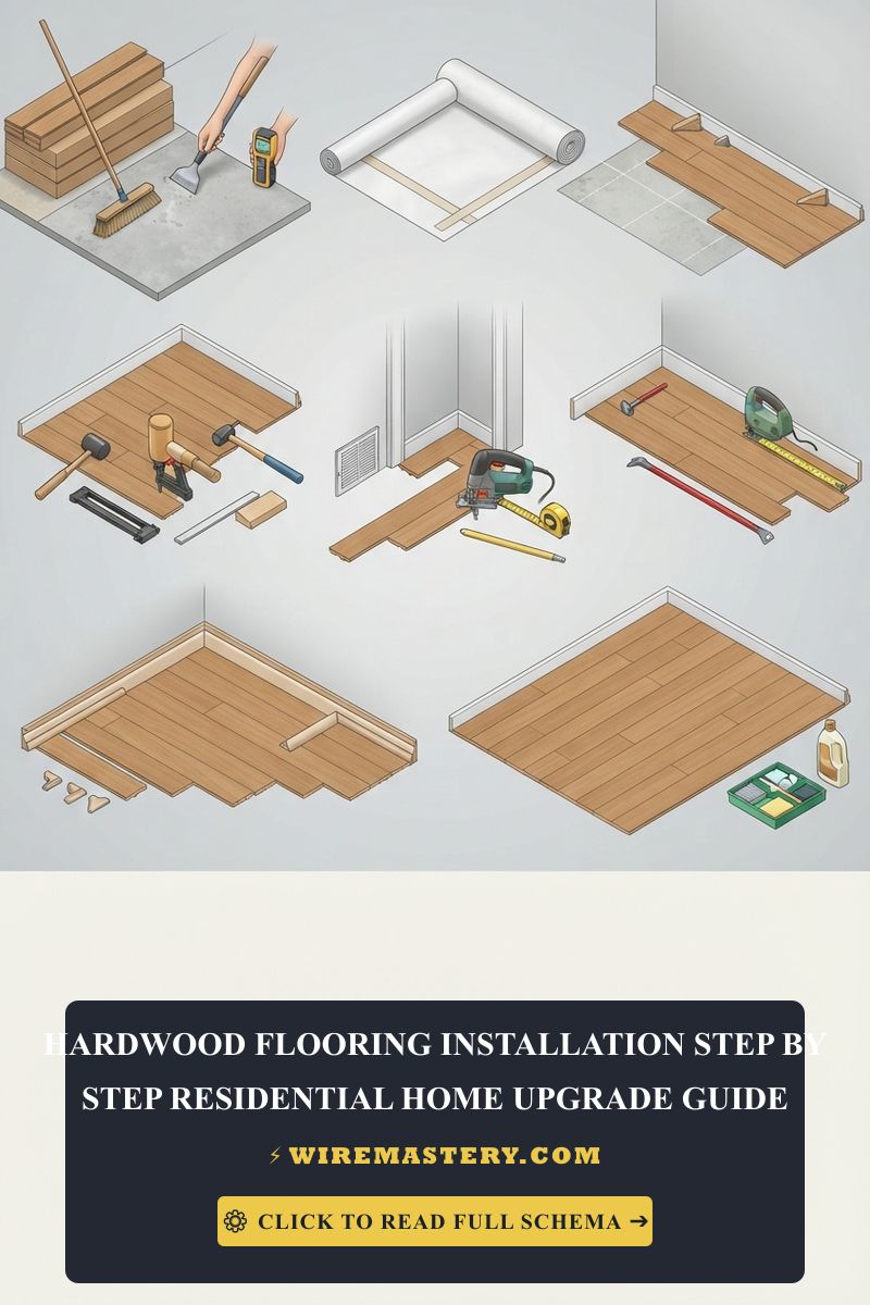
1. Subfloor Preparation and Thermal Insulation Base
- Clean the plywood or concrete subfloor surface completely until no debris, dust, or old adhesive mounds remain.
- Use a level tool to verify the subfloor is even and level. Apply an approved floor leveling compound to eliminate any dips.
- Install the Thermal Break Barrier: Lay down a high-density cork or polystyrene thermal insulation underlayment across the surface. This underlayment acts as a thermal barrier that prevents the radiant heat loops from escaping downward into the cold concrete structural earth, forcing 100% of the infrared energy to drive upward into the room.
2. Laying the Resistance Mesh Matrix and Routing the Cold-Lead Tail
- Roll out the fiberglass heating mat mesh grid slowly across the floor space. Maintain a strict 3-inch physical buffer area from all exterior walls, built-in baseboard cabinets, and structural toilet plumbing flanges to prevent localized thermal entrapment.
- The Free-Turning Mesh Hack: If you reach a corner framing obstacle, use your utility shears to slice the fiberglass mesh net. Never slice or clip the red resistance heating wire. Pivot the mat mesh 90° or 180° to clear the track, and continue rolling the element loops in parallel rows.
- Route the heavy-duty, unheated factory “cold-lead” wire tail off the floor matrix up through a rigid wall conduit track directly into a deep 4x4-inch junction wall box cavity where the thermostat will reside.
3. Placing the Dual Solid-State Floor Sensor Sonda (The Control Anchor)
- Take the low-voltage solid-state temperature sensor probe lead wire supplied with your automated digital thermostat.
- Route the probe tip directly out onto the floor mesh array, centering it physically exactly at the midpoint between two adjacent resistance heating wire loops. Secure the wire sheath to the subfloor with hot-melt glue or plastic staples.
- The Safety Backup Directive: Professional HVAC contractors always run a secondary, backup sensor probe lead alongside the first loop inside the wall channel, leaving its wire jack uncoupled in the back of the switch box. If the primary digital sensor breaks or burns out after years of hard service, you can simply plug in the standby wire without ripping up your premium finished hardwood or tile floor to replace the hardware.
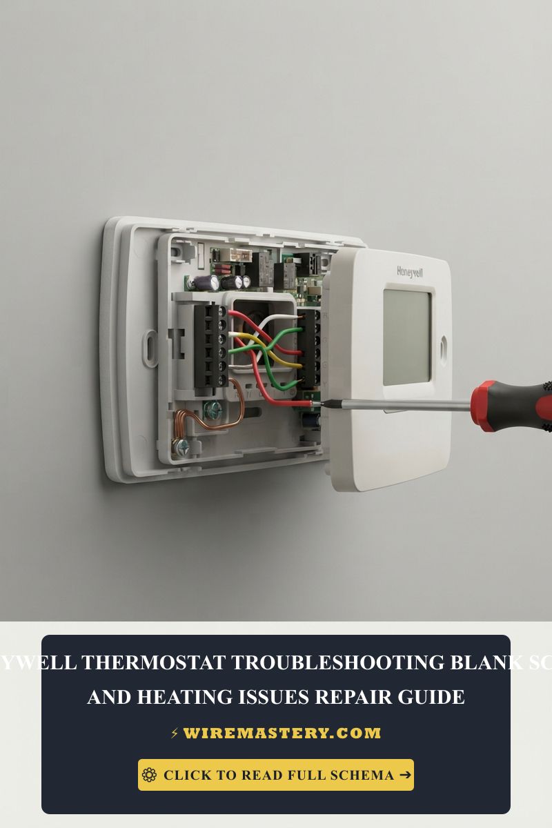
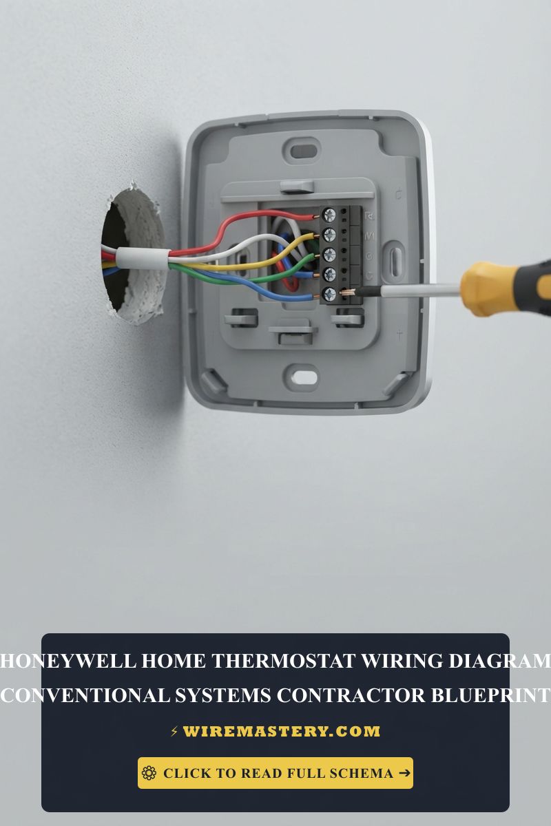
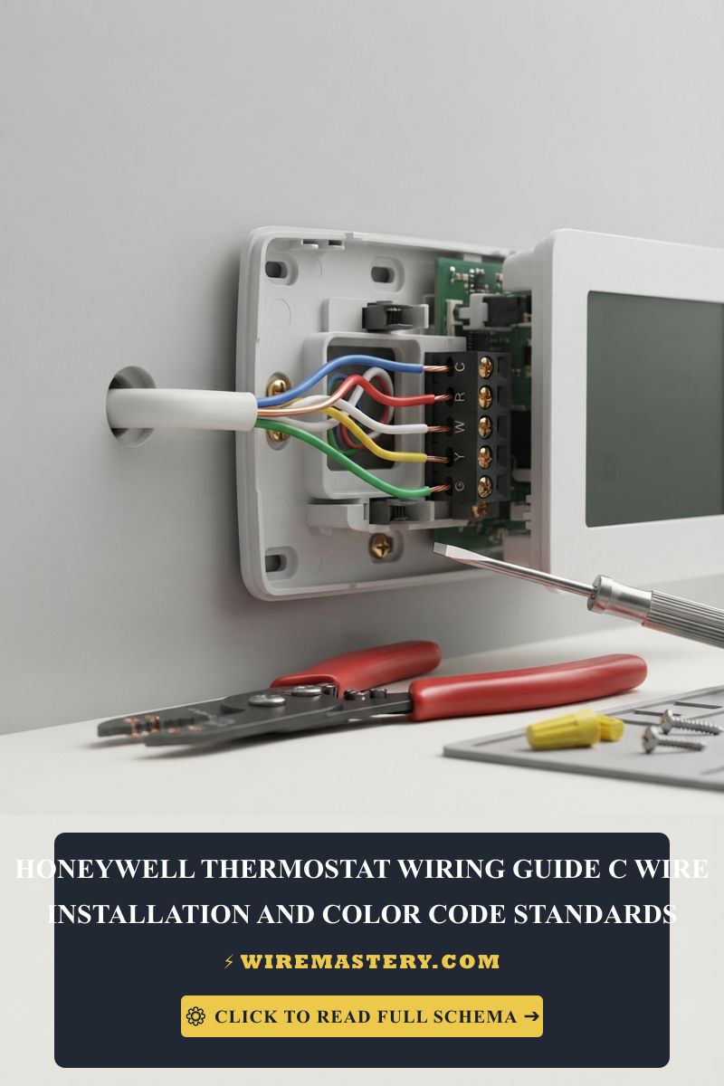
🛠️ Thermostat Ground-Fault Protection Note: Look closely at the split-phase distribution panel layouts and terminal assets showcased across our master troubleshooting portfolios. Under the mandates of NEC Article 424.44, all electric radiant floor heating systems must be protected by an integrated Class A Ground-Fault Circuit Interrupter (GFCI) engineered to trip if current leakage leaks past a tight 5 milliampere (mA) threshold margin. Modern premium radiant floor thermostats house this solid-state GFCI protection chip directly beneath their digital display screens, requiring you to attach your incoming hot and neutral feeder wires directly to the line ports to protect the space completely against shock paths.
Troubleshooting Common Floor Radiant Heating Failures
- The Floor Stays Completely Dead and the Thermostat Registers an “Open Loop” Error: This diagnostic code confirms a broken core resistance conductor wire somewhere beneath your finished floor veneer. This failure occurs when a worker steps directly onto the raw heating wire with heavy boots or scrapes a sharp metal trowel across the cable loops during the final mortar pour. Connect your multimeter in unpowered resistance mode to the lead tail; if the screen displays an infinite open loop (O.L.), the mat is open. Use a high-frequency time-domain reflectometer (TDR) fault locator instrument to pinpoint the exact square inch of the break beneath the floor to execute a microscopic tile extraction repair.
- The Connected Digital Thermostat Screen Cycles On and Off Repeatedly (Short-Cycling): This behavior indicates an active Floor Sensor Probe Error. If an apprentice installer forces the low-voltage sensor wire tight against a high-voltage 240V supply line inside the wall box channel, inductive electrical cross-talk noise will scramble the digital data packet frames. The microprocessor logic boards will fail to decode true temperature parameters, triggering safety resets. Pull the display, separate low-voltage signal tracks from power lines, or plug in your standby backup sensor probe to re-stabilize control logic.
- The Circuit Breaker Trips the Instant the Heating Cycles On: An absolute indicator of an active ground fault breakdown inside the mortar layer. This happens when the outer braided copper ground shield sheathing of the cable gets pinched tight against a metal floor lath or mesh staple, creating a low-impedance track to earth ground. Execute a high-voltage megohmmeter isolation audit at 1,000V DC to isolate the short loop segment before re-activating the subpanel.
National Electrical Code Space-Heating Regulations
Adhering to strict national installation codes protects your home investment, maintains property valuation, and ensures full property insurance compliance. The National Electrical Code strictly regulates fixed electric space-heating equipment, conductor feeds, and embedded cable arrays under NEC Article 424 (Fixed Electric Space-Heating Equipment):
- Prohibition of Element Splices (NEC 424.40): Embedded heating cables must be deployed in continuous, factory-calibrated length runs as shipped from the manufacturing plant. Executing field splices, cutting resistance conductors down to size, or paralleling independent mat leads together inside the thin-set mortar bed is a critical federal code violation that causes extreme fire hazards.
- Mandatory Ground Shield Bonding (NEC 424.43): All electric radiant heating cable loops must incorporate a continuous, factory-welded outer metal grounding shield, braid, or sheath along their entire physical lengths, which must be bonded firmly to the branch circuit equipment grounding conductor bar inside the thermostat wall enclosure box to ensure immediate overcurrent trip safety performance during a fault.
For the NFPA 70 provisions relevant to this guide on Radiant Floor Heating Installation Guide: Residential Thermal Engineering, consult the Official NFPA 70: National Electrical Code (NEC).
Conclusion
This guide covers calculating electric zone heating wattage densities under NEC Article 424 continuous load limits, executing three-stage ohmic and 1,000V DC megohmmeter insulation audits, and embedding parallel solid-state temperature backup sensor probes transforms floor climate optimization into a highly controlled, predictable science. By keeping circuit conductors fully aligned with overcurrent protection limits, preventing dangerous resistance cutting shortcuts, and enforcing strict ground-fault circuit interrupter safety boundaries around utility panels, you build an exceptionally resilient, code-compliant home environment. For final checks, complete utility subpanel power isolation checks before raw line handling, deploy certified diagnostic instruments, and complete every maintenance phase with precision.