Residential Electrical Repair: Short Circuit vs. Ground Fault
Introduction
Executing a precise, residential electrical repair on a branch circuit experiencing immediate overcurrent breaker trips demands a disciplined understanding of fault-current dynamics, low-resistance pathways, and systematic isolation logic. When a protective circuit breaker snaps to the full “OFF” position the exact millisecond you attempt a manual reset, the system is actively responding to a catastrophic fault track that bypasses normal appliance loads. Forcing or holding a tripping breaker closed repeatedly can vaporize copper conductors behind drywall sheets, leading to localized arc-flash explosions and severe building fire hazards. For properties integrating advanced automation grids, ensuring your branch lines maintain full compliance with no-neutral smart switch installation guidelines prevents intense fault-current inductive spikes from frying sensitive solid-state micro-processors.
The core engineering differences between short circuits and ground faults, the physical mechanics of low-resistance paths, and advanced diagnostic toolkit requirements.
Core Fault Engineering Thresholds
Before removing deadfront distribution covers or decoupling wire connections inside a junction box cavity, you must decode these foundational fault parameters:
-
The Short Circuit Mechanics: A short circuit occurs strictly when an ungrounded continuous Line Hot conductor (Black/Red) makes direct physical contact with a Grounded Neutral conductor (White). This layout removes all circuit loop resistance (R ≈ 0 Ω), causing active amperage draw to skyrocket to thousands of Amps instantaneously according to Ohm’s Law (I = V / R), forcing the breaker’s magnetic element to trip in milliseconds.
-
The Ground Fault Mechanics: A ground fault occurs strictly when an ungrounded Line Hot conductor breaks through its insulation layer and makes direct contact with a grounded metal element, such as a steel gang box, appliance chassis, or the bare copper equipment grounding wire.
-
The Overcurrent Response Variance: While both anomalies drop circuit resistance and trip breakers, ground faults in wet areas demand rapid detection through localized solid-state electronics to suppress high-impedance shock paths before human flesh can bridge the fault to the earth.
Technical Materials & Overcurrent Fault Isolation Toolkit
Safely tracking hidden short circuits and verifying insulation resistance profiles requires specific heavy-duty diagnostic instrumentation and insulated hand tools:
| Electrical Troubleshooting Tool | Primary Engineering Purpose & Trade Safety Rating |
|---|---|
| Digital Storage Multimeter | Category CAT III 600V certified to capture continuous low-resistance óhmic values accurately. |
| Non-Contact AC Voltage Tester | Audibly monitors the work perimeter to ensure a 100% de-energized box workspace. |
| Insulated Linesman Pliers | Hardened jaws to safely pull and isolate stiff copper leads inside cramped boxes. |
| GFCI Circuit Receptacle Tester | Plugs directly into finished ports to verify line configurations and test micro-ampere leaks. |
| High-Grade Electrical Insulation Tape | Heavy-duty PVC tape rated for 600V continuous to insulate nicked wire sections safely. |
Sizing Branch Wire Diameters & Circuit Breaker Ampacities
When executing a repair leg or replacing a component damaged by intense fault-current arc tracking, you must match your wire sizes and breaker metrics to the strict parameters of NEC Article 310.16:
- 14 AWG Solid Copper Conductor (15-Amp Breaker Limit): Standard white jacket profile. If a short circuit occurs on a 15A branch, the short-duration current spike can easily exceed 500 Amps before magnetic element separation completes.
- 12 AWG Solid Copper Conductor (20-Amp Breaker Limit): Heavy-duty yellow jacket profile. Mandatory for small appliance branch circuits (SABC) to withstand high thermal stresses during a dead short without melting surrounding conductor wraps.
Technical Phase 1: The Safe “Cold” Ohmmeter Diagnostic Protocol
The single most dangerous mistake made by amateur DIYers is repeatedly flipping a tripping breaker back on to “see where the sparks come from.” This hazardous practice creates progressive arc tracking damage. Professional contractors deploy an unpowered “Cold” resistance audit to isolate a dead short circuit safely:
1. Hard Panel Power Isolation
Go to the primary breaker panel block. Turn off and mechanically lock out the circuit breaker supplying power to the faulty branch loop. Pull forward every electrical appliance, lamp, and electronic hardware module plugged into absolutely any outlet on that entire circuit. If an appliance is left connected, its internal heating elements or transformer coils will register a false low resistance on your meter, ruining the diagnostic data.
2. Setting Up the Multimeter for Resistance Tracking
Take your digital multimeter and rotate the dial to the Resistance mode (indicated by the Ohms Ω or audible Continuity buzzer symbol). Touch your two testing probes together directly; the meter must emit a continuous high-pitched beep and display a resistance reading close to 0.0 Ω, confirming your test leads maintain pristine continuity.
3. Probing the Line-to-Neutral Boundary Loop
Go to any accessible outlet faceplate on the tripped circuit. Insert your black multimeter probe into the wide Neutral slot and your red probe into the narrow Hot slot.
- Analyze the Digital Ohmmeter Display:
- The System Reads Open Loop (O.L.): The circuit hot and neutral lines are successfully isolated from each other. The breaker trip is likely caused by an internal appliance failure or an isolated ground fault inside a metal junction box rather than a dead short circuit inside the walls.
- The System Displays Less Than 1.0 Ω (Continuous Beep): This low ohmic parameter confirms a dead short circuit. The black hot wire and white neutral wire are melted or physically pinched together somewhere behind your drywall sheets, creating a zero-resistance loop that must be physically isolated box by box.
Technical Phase 2: Sectional Isolation & Ground Fault Tracking
When your cold resistance audit confirms an active dead short or ground fault, you must systematically break the circuit branch down into individual segments to find the exact wall enclosure housing the failure.
1. The Segmented Disconnection Strategy
- Navigate to the exact physical midpoint box layout along the faulty branch run.
- De-energize the system completely and pull the outlet or switch yoke forward out of the box cavity.
- Back out the wire nuts connecting the incoming Romex lines to the downstream wire lines traveling to the rest of the room. Separate the bare copper tips completely so they float in mid-air.
- Return to your primary electrical panel board, remove your padlock clamp, and attempt to reset the circuit breaker temporarily.
- If the Breaker Trips Instantly: The short circuit or ground fault is located upstream, hidden between the panel and this midpoint box.
- If the Breaker Stays Engaged: The upstream segment is perfectly healthy. The short circuit sits downstream, buried between this midpoint box and the end of the line run. This simple bracket process eliminates 50% of your search perimeter in seconds.
2. Probing for Hidden Ground Faults to Metal Enclosures
If your line-to-neutral reading is clear but the breaker still trips under magnetic strain, an ungrounded conductor is making physical contact with a grounded chassis or bare wire line under the mandates of NEC Article 250:
- Keep the breaker turned off and locked out at the main panel.
- Rotate your multimeter to Continuity mode (Ω). Place your black probe firmly onto the side edge of a metallic gang box or the bare copper safety ground wire bundle.
- Touch your red testing probe to the isolated Black Hot conductor wire tip.
- The System Registers O.L. (Open Loop): The hot conductor insulation is structurally sound.
- The Meter Emits a Continuous Beep (Low Resistance): You have successfully pinpointed a ground fault. The hot conductor jacket has been sheared or nicked against a sharp metal stamping inside the box cavity, creating a low-impedance track to ground that must be insulated.
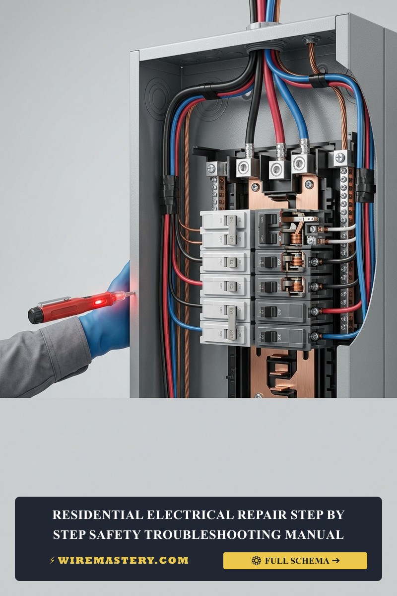
🛠️ Wire Wrapping & Packing Note: Look closely at the split-phase subpanel layouts and terminal assets showcased across our master troubleshooting portfolios. Notice that a ground fault frequently triggers when an amateur installer shoves a bulky receptacle back into a single-gang enclosure haphazardly. The bare copper grounding wire bends and presses tight against the side brass terminal screws of the outlet. Always wrap the entire perimeter of your device yokes with two tight layers of high-grade, 600V-rated electrical tape to provide an unshakeable insulation barrier over exposed side screws before packing them flat against the box rear wall.
Troubleshooting Common Overcurrent Anomalies Safely
- The Breaker Holds Power for 5 Minutes, Then Trips Suddenly: This behavior indicates a thermal circuit overload rather than a dead short or ground fault. The sum of the appliance currents connected to that line (e.g., running a portable AC unit alongside a gaming computer) is exceeding the breaker’s rated capacity limit (15A or 20A). The bimetallic strip inside the breaker slowly heats up and flexes over minutes, dropping the circuit offline. Map your active current loads and redistribute appliances across independent circuits immediately.
- The GFCI Outlet Trips Continuously Even with No Devices Plugged In: This indicate a downstream ground fault or severe moisture contamination inside an outdoor box loop. Use an electrical contact spray to flush out any water film or carbon dust bridging the terminals behind the outlet casing. If the GFCI continues to trip after cleaning, its internal sensing circuitry has suffered an inductive blowout from an active lightning surge, demanding a new, certified Tamper-Resistant replacement.
- The Arc-Fault Breaker (AFCI) Trips Instantly on Bedroom Circuits: AFCI panel breakers utilize micro-processors to detect tiny digital wave signatures caused by loose spark tracks. If an installer utilizes loose rear backstabbed holes instead of tightening the side terminal screws, the micro-arcing will trip the AFCI immediately. Pull the devices, eliminate all backstabbed connections, and torque the side screws firmly.
National Electrical Code Fault Prevention Regulations
Adhering to strict construction codes ensures your home electrical repairs remain fully insurable, legal, and property-safe. The National Electrical Code strictly regulates overcurrent fault protections, conductor insulation integrity, and junction spacing capacities under NEC Article 250 (Grounding and Bonding) and Article 314 (Outlet, Device, Pull, and Junction Boxes):
- The Effective Ground-Fault Current Path (NEC 250.4(A)(5)): Electrical systems must design an intentional, permanent, low-impedance path to facilitate the instantaneous operation of overcurrent devices during a ground fault. If your structural grounding connections are broken or un-bonded, the breaker will fail to trip, leaving exposed metal appliance handles energized with lethal line voltage.
- Box Deep Clearances and Fill Volume Limits (NEC 314.16): Overcrowding deep box enclosures causes wire insulation to scratch against sharp metal clamps when stuffing devices inward, leading to catastrophic dead short circuits inside finished walls. Always conduct a formal box volume audit to ensure your conductors maintain ample free breathing space.
For the NFPA 70 provisions relevant to this guide on Residential Electrical Repair: Short Circuit vs. Ground Fault, consult the Official NFPA 70: National Electrical Code (NEC).
Conclusion
This article explains low-resistance fault pathways, executing unpowered “Cold” ohmmeter balancing audits using CAT III certified multi-testers, and tracking down ground faults using systematic segmented isolation logic transforms hazardous electrical failures into highly predictable repairs. By keeping branch current tracks clear of parallel hot-to-neutral shorts, wrapping terminal side screws with premium electrical insulation tape to eliminate enclosure grounding shorts, and respecting mandatory NEC clearance parameters, you build an exceptionally resilient residential grid framework. For final checks, complete panel breaker power isolation safety checkups, deploy insulated trade hand tools, and complete every diagnostic step with precision.