Residential Power Systems Engineering: Phase Balancing & Microgrids
Engineering a resilient residential microgrid, integrating automated standby generator networks, or balancing thermal phase profiles across a split-phase distribution panel board demands a rigorous operational command of alternating current (AC) voltage vectors, inductive phase shifting, and synchronous transfer geometries. In standard North American residential service entrances, utility power is delivered via a three-wire single-phase loop consisting of two independent 120V hot legs (Line 1 and Line 2) wrapped around a shared grounded neutral conductor, totaling 240V line-to-line potential. When heavy fixed appliances or automated automated charging clusters cycle on, an uneven distribution of current between Line 1 and Line 2 forces the neutral conductor to carry the vector difference imbalance. Executing these layouts without proper phase balancing induces localized harmonic voltage sags, overheating transformer windings and starving downstream microchips.
This systems manual outlines the mathematical logic of split-phase load balancing, the physical wiring configurations for manual and automatic transfer switches, and advanced laboratory safety diagnostics.
Core Power Systems Engineering Parameters
Before organizing circuit layout breaker distribution tracks or handling raw service entrance lugs, establish these foundational system boundaries:
- The Phase Amperage Balance Floor: To prevent premature thermal degradation of the panel board main bus bars, the cumulative current imbalance between Line 1 and Line 2 under maximum design load conditions must stay strictly below a 10% threshold variance. Extreme phase current mismatches skew voltage parameters, causing household lights to flicker.
- The Standby Generator Isolation Mandate (NEC 702.5): Optional standby generation networks must incorporate a dedicated mechanical or solid-state Transfer Switch mechanism. Connecting a backup generator to a residential grid without an explicit break-before-make transfer configuration creates a lethal back-feeding hazard, sending 240V shooting backward through the utility transformer and electrocuting line workers down the track.
- The Continuous Loading Overcurrent Cushion: Fixed power equipment and transfer devices operating under emergency backup scenarios are classified as continuous continuous loads, requiring circuit protection and conductor size tracks to incorporate a 125% ampacity headroom cushion to suppress localized heat build-up.
Technical Materials & High-Energy Power Systems Diagnostics Toolkit
Safely verifying line-to-line phase synchronization parameters and monitoring live feeder current draws requires specific laboratory-grade instruments and protective insulation gear:
| Power Systems Auditing Tool | Primary Engineering Purpose & Safety Threshold |
|---|---|
| True RMS CAT IV Clamp Meter | Category CAT IV 600V certified to capture live feeder phase current imbalances cleanly. |
| Phase Rotation Power Tester | Verifies phase synchronization boundaries before engaging dual-source transfer lines. |
| 1000V Insulated Torque Wrench | Calibrated to torque main lugs and transfer switches to exact manufacturer inch-pound specs. |
| Non-Contact AC Proximity Tester | High-sensitivity sensor to audibly guarantee 100% bus de-energization before wire handling. |
| Class 00 Dielectric Rubber Gloves | High-density protective gloves rated to block up to 500V AC continuous contact tracks. |
Service Conductor Gauges & Branch Circuit Amperages (NEC 310.16)
When executing an emergency subpanel integration or connecting a high-capacity transfer box link, you must match your copper or aluminum wire shanks straight to the overcurrent limit defined by NEC Article 310.16 parameters:
- #10 AWG Solid Copper Conductor (30-Amp Circuit Limit): Deployed for small portable generator outlets (NEMA L14-30R). Sized inside orange sheaths; common for basic 7,500-Watt backup loops.
- #8 AWG Stranded Copper Conductor (40-Amp Circuit Limit): The baseline size for standard mid-sized residential standby power transfer blocks.
- #6 AWG Stranded Copper THHN Lines (50-Amp Circuit Limit): Mandatory diameter parameter to wire a heavy-duty NEMA 14-50 inlet box feeding a whole-house transfer module, supporting an active 40-Amp continuous current draw safely without thermal jacket melting.
Technical Phase 2: Transfer Switch Wiring & Phase Balancing Execution
Once your structural wire parameters are configured to match overcurrent limits, you must master the physical termination of mechanical transfer switches and execute a precise branch load balancing matrix across the panel bus bars.
1. Step-by-Step Field Blueprint: Wiring an Automatic Transfer Switch (ATS)
To integrate a code-compliant automatic transfer switch (ATS) to manage emergency power transitions safely, apply this systematic field installation sequence:
- Isolate Primary Utility Feeds: Contact your municipal utility company to pull the outdoor meter socket plug entirely, achieving a true zero-energy state across your main incoming lugs. Confirm 0V AC across all terminal blocks using your CAT IV multimeter.
- Mounting and Line Terminations: Mount the NEMA 3R rain-proof ATS enclosure box securely onto the wall framing adjacent to your main distribution panel center. Route your primary incoming utility line wires directly into the terminal lugs stamped UTILITY LINE 1 and UTILITY LINE 2.
- Connecting the Standby Power Source: Route your heavy stranded generator THHN lines into the ports stamped GENERATOR LINE 1 and GENERATOR LINE 2. Secure the outgoing feeder lines straight to the main panel lugs, and connect the low-voltage multi-conductor signaling harness to the generator’s automated startup control board.
- The Switched Neutral Requirement (NEC 702.11): If your standby generator features an internally bonded neutral-to-frame configuration (Separately Derived System), you must install an ATS equipped with a switched neutral terminal pole. This design forces the neutral line to break and transfer concurrently with the hot phases, preventing hazardous parallel return paths to ground.
2. Executing a Balanced Phase Matrix Audit
To resolve chronic neutral wire overheating and voltage fluctuations, an engineer maps out branch current draws systematically using a True RMS clamp ammeter:
- Turn on all heavy household appliances to establish a peak operational loading baseline.
- Clamp your meter jaws around the Line 1 feeder conductor inside the panel gutter and record the active Amperage. Clamp the meter around the Line 2 feeder conductor and note the variance.
- The Load Relocation Protocol: If Line 1 registers 65 Amps while Line 2 floats at 22 Amps, you have a critical phase imbalance. Identify your high-draw 120V single-pole loads (such as microwave ovens or space heaters) currently occupying adjacent slots on the Line 1 bus rail. Relocate these specific circuit breakers down to alternating slots connected to the Line 2 bus rail until the current differentials drop below the 10% threshold safety ceiling, neutralizing voltage sags.
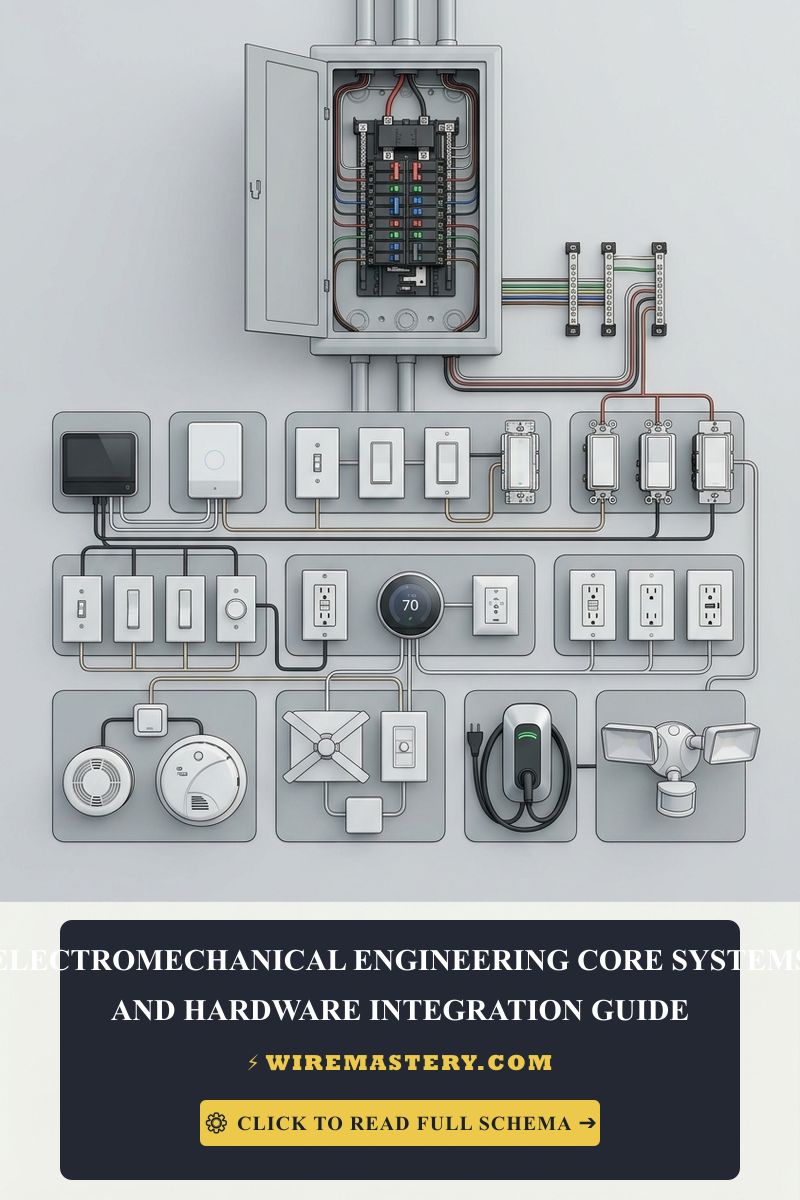
🛠️ The Multi-Contact Mechanical Interlock Note: Look closely at the manual transfer subpanel layouts showcased across our master electrical installation portfolios. Notice that if your renovation project utilizes an economy manual transfer switch instead of an automated ATS block, building safety regulations strictly mandate installing a mechanical slider plate interlock device directly over the panel faceplate framing. This physical barrier mechanically blocks the user from ever sliding the backup generator breaker handle to “ON” while the primary utility main breaker is engaged, preventing lethal back-feeding explosions.
Troubleshooting Common Power System Anomales
- The Generator Starts but the ATS Fails to Transfer Power Inside: This behavior indicates a severe control circuit voltage drop or an out-of-phase synchronization fault. If your low-voltage startup signaling lines are routed inside the same conduit tracks as high-voltage generator feeder wires, intense electromagnetic cross-talk noise will scramble the digital logic packets. The ATS microprocessor logic boards will fail to confirm stable frequency parameters (60 Hz), locking out the internal mechanical plunger. Separate low-voltage tracks immediately to restore control logic.
- The Main Panel Neutral Wire Discolors or Smells of Plaster Scorching: An absolute indicator of a Catastrophic Phase Imbalance or an Un-bonded Service Neutral. If an installer grouped all single-phase high-density appliance loads onto Line 1 exclusively, the neutral conductor is forced to absorb the total return current without vector cancellation. Check your lugs with a thermal laser scanner; if the neutral lug registers a temperature exceeding 140°F (60°C), shut down the main disconnect and rebalance your breaker positions across the phases immediately.
- The Standby Generator Stalls the Instant the Transfer Switch Engages: This symptom confirms a Locked Rotor Inrush Overload fault. You have failed to configure a dedicated Load Shedding Management Relay matrix. High-draw components (like central AC compressors or water heaters) are attempting to initialize concurrently, generating an inrush current spike that exceeds the generator’s peak kilowatt surge headroom. Program digital load-shed delays to step the appliance entries sequentially.
National Electrical Code Standby Power System Regulations
Adhering to strict national structural regulations protects your home infrastructure from electrical fire hazards, maintains full property insurance validity, and ensures complete property safety compliance. Standby power infrastructures and generator networks are heavily cross-regulated under NEC Article 702 (Optional Standby Systems) and Article 445 (Generators):
- The Line-of-Sight Disconnect Mandate (NEC 445.18): Generators must be equipped with one or more physical mechanical disconnecting means switch handles capable of being locked in the absolute open “OFF” position. This disconnect must be installed within clear, un-obstructed line-of-sight of the generator frame, ensuring field service technicians can instantly slice power during an emergency kinetic crisis.
- Capacity and Rating Limits (NEC 702.4): An optional standby system must have adequate capacity and rating to supply all equipment intended to be operated at one time. Hired general contractors must perform a formal written load calculation sheet under NEC Article 220 to prove the standby source can legally absorb the target footprint before executing wire cuts.
For the NFPA 70 provisions relevant to this guide on Residential Power Systems Engineering: Phase Balancing & Microgrids, consult the Official NFPA 70: National Electrical Code (NEC).
Conclusion
This guide covers calculating split-phase load balancing matrices, configuring code-compliant automatic transfer switches (ATS) with synchronized phase-switching logic, and enforcing separate neutral-ground isolation paths transforms complex residential power infrastructure engineering into a highly predictable, science. By keeping conductor cross-sections fully aligned with NEC Article 310.16 continuous overcurrent limits, installing mechanical interlock slider blocks to eliminate hazardous utility back-feeding loops, and respecting mandatory NEC workspace spatial envelopes, you build an exceptionally resilient, safe home grid ecosystem. For final checks, complete utility subpanel power isolation safety protocols before opening electrical gutters, deploy CAT IV certified digital clamp meters, and complete every technical termination phase with safety-first precision.