DIY Home Electrical Repair: Fixing Burnt Junction Box Wiring
Introduction
Executing residential DIY home electrical repairs inside a damaged or overcrowded junction box demands a methodical approach that prioritizes code compliance, thermal mitigation, and circuit balancing. When a high-draw appliance circuit encounters localized high resistance due to a loose wire nut splice or an improperly torqued terminal screw, the electrical pathway transforms into a miniature heating element. Over time, this resistance causes severe micro-arcing, destroying nylon conductor jackets, melting plastic wire connectors, and leaving brittle, carbon-scorched copper leads inside the wall framing. Bypassing clear repair guidelines will compromise structural insulation layers and violate federal building fires safety standards.
This restoration manual outlines professional diagnostics for hidden arc faults, precise methods for cutting back and stripping thermal-damaged solid copper cores, and step-by-step wire-splicing protocols.
Core Structural Repair Parameters
Before slicing into damaged multi-conductor branch lines or resetting an overcurrent protection device, verify these engineering baselines:
- The 6-Inch Conductor Mandate: Under NEC Article 300.14, every electrical junction box must contain a minimum of 6 inches of free conductor length measured from its point of entry into the box enclosure. This parameter ensures ample physical length to manipulate wires and execute tight, safe pigtail terminations.
- The Carbon Arc Failure Point: Carbon soot deposits left behind by melted wire jacket insulation are highly conductive. Failing to cut back a scorched conductor until reaching clean, shiny pink copper creates a high-resistance fault path that will arc again immediately under sustained loads.
- Class 2 Circuit Isolation Boundaries: Ensure that any power lines you are repairing do not pass through enclosures containing low-voltage automation tracks or data signal lines without certified physical metallic dividers.
Technical Materials & Burned Circuit Restoration Toolkit
Safely opening scorched electrical enclosures and re-engineering low-resistance wire splices requires specific heavy-duty trade hand tools and testing instrumentation:
| Electrical Restoration Tool | Primary Engineering Purpose & Trade Application |
|---|---|
| Non-Contact AC Voltage Tester | Essential safety tool to confirm 100% circuit de-energization before touching any wiring. |
| Heavy-Duty High-Leverage Linesman Pliers | Engineered with hardened cutting jaws to shear through brittle, overheated copper wires cleanly. |
| Ergonomic Precision Wire Strippers | Calibrated to remove PVC outer jackets smoothly off #14 AWG and #12 AWG solid copper cores. |
| Digital True RMS Multimeter | Measures line-voltage drops, load currents, and monitors ground loop continuity paths. |
| UL-Listed Twist-On Wire Connectors | Rated for specific maximum combination fills to clamp copper strands under internal spring tension. |
Sizing Wire Gauges & Ampacity Layout Rules (NEC Article 310.16)
When executing an emergency patch or splicing an extension leg to restore a damaged branch run, you must match your replacement wire sizes exactly to the circuit’s overcurrent protection breaker rating. Utilizing thin wire profiles on heavy circuit loads creates high-resistance hotspots inside framing structures:
- 14 AWG Solid Copper Conductor: Rated exclusively for 15-Amp circuits. Wrapped inside white protective sheaths, it is used for general residential lighting lines.
- 12 AWG Solid Copper Conductor: Rated for 20-Amp circuits. Wrapped inside yellow sheaths, it is mandatory for kitchen small appliance branch circuits (SABC) and bathroom loops.
- 10 AWG Solid Copper Conductor: Rated for 30-Amp circuits. Wrapped inside orange sheaths, it is required for dedicated electric clothes dryers and central AC condenser lines.
Troubleshooting Phase: Diagnosing a Damaged Junction Box Loop
Amateur installers often wait until an outlet fails completely before checking their lines, ignoring clear visual and acoustic warning triggers that indicate a progressive melting event inside the drywall cavity:
1. The Acoustic Arc Screening Test
Turn on the heavy appliances tied to the target branch circuit. Stand near the wall switch or junction outlet box and listen closely. If you detect a faint sizzling, frying, or intermittent buzzing noise, the wire nut connections have loosened. High-voltage current is actively jumping across a physical air gap, creating destructive micro-arcs that are cooking the internal wire nuts.
2. The Thermal Faceplate Inspection
If the plastic faceplate or the drywall area surrounding an electrical box enclosure feels warm to the touch, or emits a distinct acrid, chemical-like odor resembling burnt fish, turn off the breaker immediately. Plastic jacket components are actively degenerating under extreme thermal loading.
3. The Digital Voltage Drop Audit
If a receptacle exhibits unstable power outputs, use your digital multimeter to verify line health:
- Insert your multimeter probes into the hot and neutral slots of the target outlet face.
- Turn on a high-draw appliance (like a hairdryer or space heater) on an adjacent plug along the same line loop.
- Analyze the Voltage Sag: If your line voltage drops from a healthy 120V AC down below 108V AC (exceeding a 5% drop), you have a high-resistance splice somewhere along the run that is choking the current loop and generating massive heat.
Step-by-Step Restoration Protocol: Re-Engineering Scored Junction Box Wiring
Once your diagnostics phase pinpointed the location of a melting or high-resistance wire nut loop, apply this strict field sequence to restore structural current capacity safely:
1. Hard Panel Circuit Isolation
Navigate to your property’s main distribution box and disengage the dedicated circuit breaker toggle feeding the area. Lock out the panel door to ensure no one toggles the line back on while you are raw-handling components. Prior to removing the box cover, press your non-contact tester around all side terminals to confirm a absolute 0V AC state.
2. Dissecting the Damaged Splice and Cutting Back Scorched Lead Lines
- Unwind the melted plastic wire nuts using your lineman pliers.
- Inspect the copper conductors closely. If the copper exhibits a blackened, brittle carbon coating or if the nylon casing has curled into an ash-like crust, you must prune the wire back.
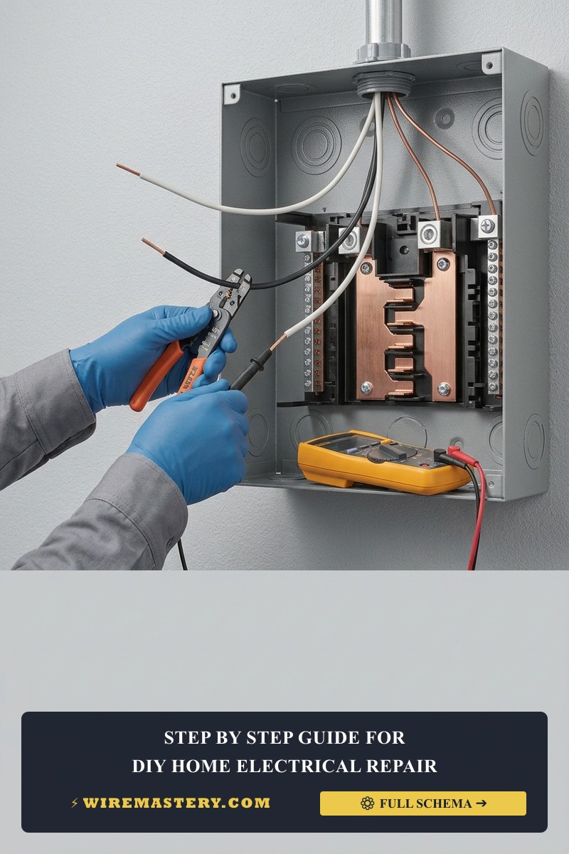
- Use the hardened cutting blades of your linesman pliers to slice away the compromised wire sections completely. Continue pruning back down the line track until you reach clean, ductile, shiny pink-colored copper cores.
3. Enforcing the 6-Inch Conductor Margin (The Extension Splice)
If cutting back the damaged conductors leaves you with less than the 6 inches of free wire required by NEC Article 300.14, you cannot legally connect your outlet or switch directly. You must fabricate an extension leg utilizing the Pigtail Splicing Method:
- Cut an identical 6-inch segment of fresh solid copper conductor wire from your spare Romex spool, matching the original wire size exactly (#12 AWG for 20A loops, #14 AWG for 15A loops).
- Use your precision strippers to remove exactly 3/4 inch of insulation off the ends of the wall wire and your new extension piece.
- Hold the two exposed copper tips side-by-side using the tips of your linesman pliers. Twist the pliers clockwise firmly to twist the solid copper shanks around each other in a clean, tight, uniform mechanical helix pattern.
- Cap the twisted connection with a high-quality, UL-listed twist-on wire nut. Twist the connector clockwise until the internal steel spring bites into the copper cores and locks the assembly under mechanical tension. Repeat this step for the Hot, Neutral, and Ground pathways.
🛠️ Junction Box Capacity Assessment Note: Look closely at the fotorrealista mockup blueprints showcased across our technical repair documents. Notice that a clean connection layout requires arranging wires flat against the rear wall of the box cavity. When executing repair loops inside a multi-conductor gang enclosure, always double-verify that your wire nuts do not press aggressively against the plastic side margins of the box, preventing structural cracking over long temperature expansion cycles.
Avoiding Critical Splicing Pitfalls & Fault Modes
- Relying on Loose Hand Twists Without Pliers: A major installation error is simply pushing wires into a wire nut and expecting the plastic shell to twist the copper together. If the mechanical bond is loose, current passing through under heavy load will create localized micro-arcs, restarting the carbon melting loop inside your drywall. Always twist conductors tightly with your linesman pliers before capping them.
- Mixing Dissimilar Conductors Safely: If you encounter old aluminum wiring interfacing with modern copper branches during a home renovation, never twist aluminum and copper together inside a standard wire nut. The two dissimilar metals undergo galvanic corrosion, creating extreme resistance and major fire hazards. You must deploy specialized, purple UL-listed AlumiConn connectors pre-filled with antioxidant joint compound to isolate the phases legally under NEC Article 110.14.
- Violating the 3-Inch Box Clearance Threshold: Under NEC 300.14, at least 3 inches of free conductor must extend past the exterior face of the finished wall opening. Keeping wires short forces technicians to work cramped inside dark boxes, leading to loose screws and un-insulated bare copper exposures.
National Construction Codes & Safety Standards
Adhering to strict electrical installation codes shields your home investment, maintains property valuation, and ensures full insurance compliance. The National Electrical Code strictly regulates general residential wiring repairs, device grounding, and junction box sizing parameters under NEC Article 300 (Wiring Methods), Article 314 (Outlet, Device, Pull, and Junction Boxes), and Article 110 (Requirements for Electrical Installations):
- Box Fill Volumes (NEC 314.16): Adding repair pigtails and extra wire connectors increases the cubic-inch count inside an enclosure cavity. Ensure your junction box has adequate internal depth volume to handle the wire density safely; stuffing conductors tightly to clear space violates fire safety boundaries.
- Accessibility Mandates (NEC 314.29): Every junction box containing an electrical splice must remain 100% accessible for future inspection and maintenance. Splicing burnt wires inside a box and then burying the enclosure behind solid drywall sheets or plaster coatings is a catastrophic federal code violation.
For current NFPA 70 guidance on residential repair work, conductor sizing, box fill, grounding, and safe circuit isolation, consult the Official NFPA 70: National Electrical Code (NEC).
Conclusion
This guide covers executing residential DIY home electrical repairs and restoring burnt junction box connections upgrades your property’s infrastructure durability and ensures full alignment with modern safety codes. By trimming back carbon-scorched conductor tips until reaching shiny copper, enforcing the mandatory 6-inch free wire extension loops through expert pigtail splicing techniques, and respecting NEC box fill and accessibility thresholds, you build an unshakeable, electrical network. For final checks, complete circuit breaker power isolation safety testing, utilize CAT III multimeters, and execute every terminal step with precision.