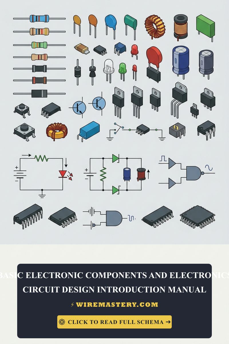
Basic Electronic Components: An Introduction to Circuit Design
Mastering the core behavior of basic electronic components is the foundation of hardware engineering and advanced troubleshooting. While residential electricians deal with heavy power distribution networks, modern automation controls, smart thermostats, and solar inverters are entirely driven by micro-electronics. Understanding how discrete components manipulate currents inside low-voltage printed circuit boards (PCBs) transforms your troubleshooting skills from generic component-swapping to precise engineering diagnostics.
This guide outlines the functions, configurations, and prototyping toolsets required to design and interpret basic electronic circuits safely.
Core Hardware Prototyping Checklist
Before applying power to a newly assembled prototype board, verify these baseline electronic metrics:
- Component Ratings: Ensure every resistor, capacitor, and semiconductor matches or exceeds the circuit’s maximum operating voltage and power dissipation (I²R) thresholds.
- Polarity Constraints: Electrolytic capacitors, diodes, and integrated circuits must be mounted in the correct physical orientation to prevent component explosion or immediate hardware failure.
- Static Discharge Controls: Modern microchips are highly vulnerable to Electrostatic Discharge (ESD). Always utilize a grounded wrist strap when handling sensitive semiconductor components.
Technical Materials & Prototyping Equipment Checklist
Building and diagnostic testing of low-voltage electronic circuits requires specific benchtop instrumentation distinct from heavy electrical trade gear:
| Electronics Bench Tool | Primary Engineering Purpose |
|---|---|
| Solderless Breadboard | A reusable plug-and-play platform to prototype and test circuit configurations without soldering. |
| Temperature-Controlled Iron | Supplies localized heat to form low-resistance mechanical alloy joints using lead-free solder. |
| Digital Auto-Ranging Multimeter | Measures millivolts, microamps, and discrete component resistances (1Ω to 10 MΩ). |
| Digital Storage Oscilloscope | Visualizes real-time voltage waveforms, frequency dropouts, and signal noise over time. |
Micro-Hardware Foundations: Core Electronic Components
To design or trace any low-voltage electronic schematic, you must decode the fundamental roles of the six foundational building blocks of electronics:
1. Resistors (Current Limitation)
Resistors introduce calculated electrical resistance into a circuit to restrict current flow and establish precise voltage drops.
- Fixed Resistors: Maintain an immutable resistance value, decoded via standard international color-coded bands.
- Variable Resistors (Potentiometers): Allow manual resistance adjustments, commonly used for volume controls or calibration trimmers.
- Key Metrics: Measured in Ohms (Ω). Standard values range from current-limiting 220Ω links to high-resistance 100kΩ pull-up tracks.
2. Capacitors (Energy Storage & Filtering)
Capacitors function as micro-batteries that transiently store and discharge electrical energy within an electrostatic field.
- Electrolytic Type: Cylindrical, highly polarized components required for smoothing out voltage ripples inside DC power supplies.
- Ceramic Type: Small, non-polarized discs optimized for high-frequency signal decoupling and noise suppression.
- Key Metrics: Measured in Farads (typically microfarads, µF, or picofarads, pF).
3. Inductors (Magnetic Filtering)
Inductors consist of insulated copper wire coils that store electrical energy inside a magnetic field when current passes through them. They naturally oppose sudden changes in current, making them exceptional low-pass filters for filtering electromagnetic interference (EMI) inside power conditioning stages.
4. Diodes (One-Way Valves)
Diodes act as electrical one-way valves, forcing current to flow in a single direction while completely blocking reverse bias currents.
- Schottky/Standard Diodes: Used for power rectification (converting alternating current to direct current).
- Zener Diodes: Engineered to break down safely in reverse bias at a precise voltage window, operating as highly reliable voltage regulators.
5. Transistors (Electronic Switching & Amplification)
The absolute cornerstone of modern computing, transistors function as solid-state electronic switches or signal amplifiers. If you are preparing an industrial control layout, consult our advanced BJT transistor switching manual to trace characteristic curve configurations.
6. Integrated Circuits (System Hubs)
Integrated Circuits (ICs) consolidate hundreds of thousands of micro-resistors, capacitors, and transistors onto a single tiny silicon wafer chip. These range from simple 555 timer modules to high-frequency microcontrollers executing thousands of programming lines per second.
Strategic Circuit Architecture: Series vs. Parallel
When planning a circuit layout, the geometrical arrangement of your components dictates the voltage distribution and current behavior under Ohm’s Law (V = I × R):
Series Configuration (Single-Track Loops)
Components are wired end-to-end in a single continuous path.
- Current Behavior: The current (I) remains identical through every single component.
- Voltage Behavior: The total voltage splits across the components based on their individual resistance ratios (V_total = V_1 + V_2 + V_3 ). If one component fails open, the entire loop goes offline immediately.
Parallel Configuration (Independent Branching)
Components are wired side-by-side across the shared electrical terminals.
- Current Behavior: The total current splits across the branches; paths with lower resistance draw higher amperage.
- Voltage Behavior: The voltage (V) remains perfectly identical across all parallel branches (V_total = V_1 = V_2). If one branch breaks, the remaining lines stay fully operational.
Step-by-Step Electronics Prototyping Blueprint
1. Schematic Capture and Simulation
Draw your complete circuit layout using a standard CAD software suite. Trace all interconnection pathways and cross-check the power dissipation limits of your resistors (P = V × I) to ensure you don’t burn out miniature quarter-watt resistors.
2. Solderless Breadboard Validation
Transfer your blueprint to a physical breadboard. Insert your component leads into the inner spring-clip terminal rows. Use solid 22 AWG jumper wires to tie your rails together. Connect a regulated low-voltage DC power supply (such as 3.3V or 5V) to the outer power bus strips.
3. Debugging and Continuity Verification
Prior to soldering a permanent PCB, use your digital multimeter to verify correct input voltages. Check for accidental short circuits between your positive voltage rails and ground tracks. If your circuit manipulates signal data frequencies, clip your oscilloscope probes onto the output nodes to verify waveform integrity.
National Electrical Safety and Infrastructure Context
While individual low-voltage breadboard electronic circuits (operating under Class 2 limitations below 30V AC / 60V DC) do not fall under the direct structural installation rules of the National Electrical Code (NEC), any system that connects to building power mains must maintain absolute code isolation. Power transformers, AC-to-DC converters, and metal chassis enclosures must comply with NEC Article 725 (Remote-Control, Signaling, and Power-Limited Circuits) to guarantee that low-voltage communication lines never make contact with dangerous high-voltage branch power circuits inside walls.
For current guidance on electronic component safety, circuit design, and applicable electrical installation requirements, consult the Official NFPA 70: National Electrical Code (NEC).
Conclusion
Successfully understanding basic electronic components and mastering circuit design concepts steps up your technical diagnostics capability and expands your engineering horizons. By decoding resistor color codes, matching capacitor polarities, and utilizing solderless breadboard prototyping methods, you construct high-performance electronic networks with absolute confidence. Prioritize input rail voltage testing, protect components from static dropouts, and design every circuit with systematic precision.







