Cat-5e Ethernet Cable Termination: Color Code & Wiring Diagram
Ethernet technology remains the absolute backbone of modern high-speed residential networking. While wireless systems offer convenience, achieving flawless local gigabit speeds and eliminating latency demands a dedicated solid-copper hardwired infrastructure. Properly terminating Category 5e (Cat-5e) data cables is the deciding factor between a multi-gigabit smart home framework and a network plagued by constant packet drops.
Maintaining flawless network packet data transfers requires more than clean RJ45 terminations; it demands absolute power stability for your central routing hardware. Home network administrators should implement a dedicated battery backup for home office configurations to protect core servers and active modems during sudden residential grid blackouts.
The exact pinout wiring diagrams for T568A and T568B color code standards, specialized crimping tool workflows, and low-voltage cable isolation regulations in compliance with the National Electrical Code (NEC).
Key Technical Specifications Checklist
Before stripping your twisted-pair data lines, verify your hardware thresholds:
- Bandwidth Capacity: Engineered up to 100 MHz to support data rates up to 1 Gbps (Gigabit per second).
- Maximum Cable Run: Limited to exactly 100 meters (328 feet) before signal attenuation requires a powered switch.
- Conductor Dimension: Typically utilizes 24 AWG solid or stranded copper conductors wrapped in four balanced twisted pairs.
Technical Materials and Tools Checklist
Executing professional network terminations requires specialized low-voltage telecommunication tools:
| Networking Tool | Primary Technical Purpose |
|---|---|
| RJ45 Crimping Tool | To compress the copper pins of the connector into the raw wire strands securely. |
| Coaxial/Data Stripper | Scores the outer PVC jacket cleanly without nicking the inner insulation. |
| Flush Wire Cutters | Trims all eight conductors completely level before insertion into the plug face. |
| Impact Punch-Down Tool | Terminates and trims raw conductors inside keystone jacks and patch panels. |
| Digital Cable Tester | Emits sequential mapping signals to verify continuity and identify crossed pairs. |
Cat-5e Color Code Matrices: T568A vs. T568B Standards
According to the official structural cabling standards regulated by the Telecommunications Industry Association (TIA), residential and commercial networks must follow the precise pinout configurations defined under the T568A or T568B color-code matrix. Aligning your hardware architecture with these official engineering frameworks guarantees full gigabit bandwidth performance and ensures multi-vendor equipment compatibility.
To ensure multi-vendor hardware compatibility, residential and commercial infrastructures rely on these matrices. While both perform identically across the network layer, you must maintain absolute consistency across both ends of the cable run to avoid creating crossover wiring faults.
The T568A Pinout Matrix (Standard Residential)
The T568A color sequence is highly favored in new residential construction installations due to its direct backward compatibility with legacy USOC telephone wiring systems.
| Pin Number | Conductor Color Code | Technical Function |
|---|---|---|
| Pin 1 | White / Green Stripe | Transmit + (TX+) |
| Pin 2 | Green Solid | Transmit - (TX-) |
| Pin 3 | White / Orange Stripe | Receive + (RX+) |
| Pin 4 | Blue Solid | Telephony / PoE Power |
| Pin 5 | White / Blue Stripe | Telephony / PoE Power |
| Pin 6 | Orange Solid | Receive - (RX-) |
| Pin 7 | White / Brown Stripe | High-Speed Data / PoE Return |
| Pin 8 | Brown Solid | High-Speed Data / PoE Return |
The T568B Pinout Matrix (Commercial Standard)
The T568B color sequence is the most prevalent standard found in existing enterprise networks and modern pre-wired patch bays.
| Pin Number | Conductor Color Code | Technical Function |
|---|---|---|
| Pin 1 | White / Orange Stripe | Transmit + (TX+) |
| Pin 2 | Orange Solid | Transmit - (TX-) |
| Pin 3 | White / Green Stripe | Receive + (RX+) |
| Pin 4 | Blue Solid | Telephony / PoE Power |
| Pin 5 | White / Blue Stripe | Telephony / PoE Power |
| Pin 6 | Green Solid | Receive - (RX-) |
| Pin 7 | White / Brown Stripe | High-Speed Data / PoE Return |
| Pin 8 | Brown Solid | High-Speed Data / PoE Return |
Step-by-Step RJ45 Termination Manual
1. Preparing the Outer Jacket
Insert the Cat-5e cable into the data stripper. Score the outer PVC sheath approximately 1.5 inches from the cable end. Rotate the tool gently and pull the jacket away. Inspect the internal twisted wires closely under a bright light; if the metal stripper blade nicked the colored insulation, cut the cable back completely and re-strip to avoid a hidden short circuit.
2. Arranging and Aligning the Conductors
Separate the four twisted pairs. Untwist the conductors down to the jacket termination point. Using your fingers, straighten the eight internal wires until they sit completely flat. Arrange them from left to right following your chosen TIA standard sequence (T568A or T568B). Use your flush cutters to snip the wires perfectly perpendicular, leaving exactly 1/2 inch of exposed conductors.
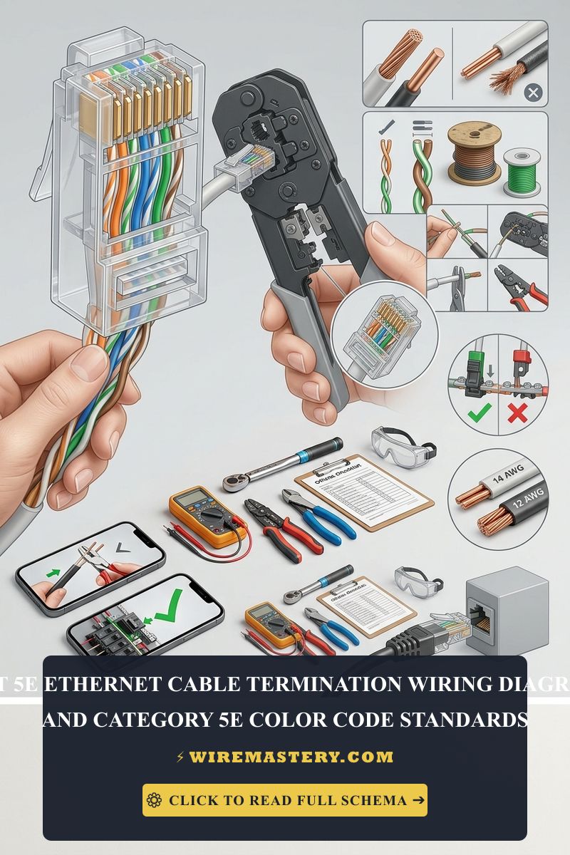
🛠️ Network Engineering Tip: Look closely at the transparent RJ45 plug design shown in your guide assets. The internal twisting ratio of the copper pairs is engineered precisely to suppress near-end crosstalk (NEXT). To ensure full Gigabit bandwidth certification, never untwist the internal pairs more than 1/2 inch away from the point where they exit the outer jacket.
3. Insertion and Crimping Execution
Hold the RJ45 connector with the plastic locking tab facing downward. Push the straightened wire sequence firmly into the back of the plug until the raw copper tips rest flush against the transparent front plastic window. Double-check that the outer PVC jacket extends past the internal plastic strain relief wedge. Insert the connector into your crimping tool cavity and compress the handles firmly to drive the gold-plated teeth directly through the conductor coatings.
4. Wall Jack Punch-Down Execution (Cat5e Socket Wiring Diagram)
If your installation requires terminating a wall outlet rather than a patch cable, you must follow a cat5e socket wiring diagram using an impact punch-down tool:
- Locate the color-coded T568A and T568B color matrices printed directly on the plastic sides of your keystone jack framework.
- Maintain the tight wire twists up to the terminal slots and use the punch-down tool with the cutting blade facing outward to compress and slice the excess copper wire leads cleanly.
Troubleshooting Common Termination Faults
- Cable Fails Continuity Test: If your cable tester reveals missing pin signals, it is usually caused by under-crimping or a wire that didn’t reach the front window of the RJ45 plug. Cut the connector off and repeat the termination process carefully.
- Severe Signal Latency or Packet Loss: This occurs when installers run data lines parallel to high-voltage residential power lines. Ensure your low-voltage data cables cross high-voltage lines at a strict 90-degree angle to avoid magnetic field interference.
- PoE Devices Disconnect Randomly: Power over Ethernet (PoE) equipment requires low-resistance connections. Ensure you are sourcing Solid Bare Copper Cat-5e lines rather than cheap Copper Clad Aluminum (CCA) cables, which suffer from massive voltage drops.
NEC Code Compliance for Low-Voltage Data Cabling
Adhering to official structural codes ensures your smart home network remains legal and fire-safe. The National Electrical Code strictly regulates data installations under NEC Article 800 - Communication Circuits:
- Fire Separation Thresholds: Low-voltage data lines must maintain a minimum 2-inch physical separation from any high-voltage branch power circuits inside wall cavities unless enclosed in approved conduits.
- Jacket Safety Ratings: Wires passing through residential walls or structural floors must be rated as CM (General Purpose) or CMP (Plenum Rated) to guarantee the outer PVC sheath self-extinguishes during a fire and does not emit toxic smoke.
For current guidance on Cat 5e cable pathways, low-voltage separation, and communications wiring, consult the Official NFPA 70: National Electrical Code (NEC).
Conclusion
Successfully terminating a Cat-5e network cable steps up your residential bandwidth capability and builds an unshakeable infrastructure for your smart home devices. By tracking your T568A/T568B pinout color codes, maintaining tight copper wire twists, and respecting NEC Article 800 safety isolation limits, you construct a professional, commercial-grade home grid. Prioritize clean crimping steps, validate with your digital continuity tester, and enjoy reliable gigabit speeds.