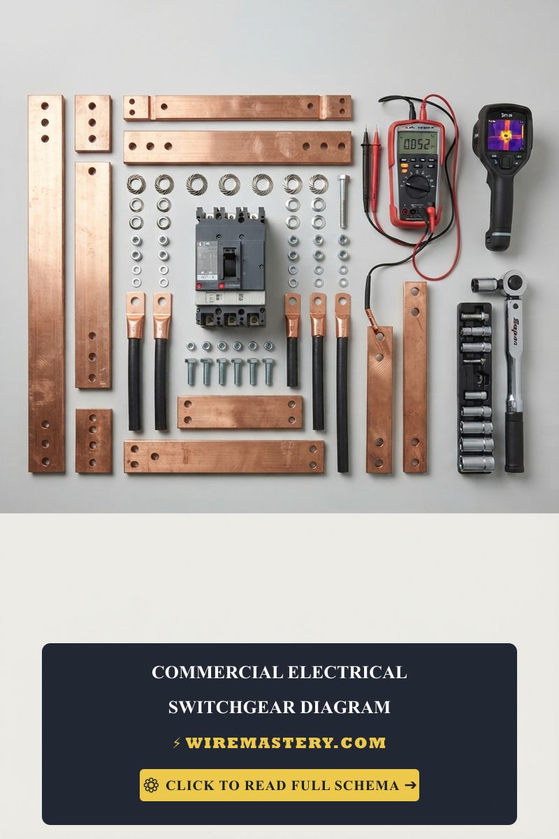
Commercial Electrical Switchgear Diagram: Sizing & Wiring Manual
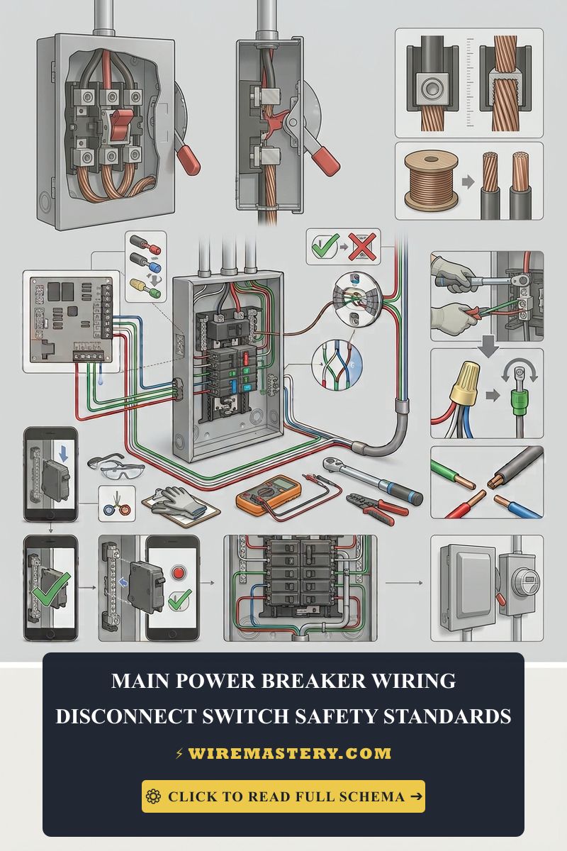
Engineering a resilient heavy-power industrial facility or managing multi-phase service entrants across contemporary high-density manufacturing hubs requires an absolute operational command of centralized high-voltage distribution networks, fault-current mitigation architectures, and complex electromechanical schematics. Within utility-scale engineering frameworks, analyzing an official commercial electrical switchgear diagram represents the primary defensive boundary between seamless service continuity and a catastrophic arc-flash detonation inside primary facility service panel boards. Large-scale enterprise grids cannot rely on standard light-duty residential breaker enclosures; instead, they integrate multi-section, floor-mounted metal-enclosed assemblies designed to receive, monitor, and partition megawatts of raw utility potential. Miscalculating structural bus bar spacings or utilizing unverified grounding parameters under continuous load states causes accelerated dielectric breakdown, leading to progressive insulation degradation that triggers explosive phase-to-phase faults before secondary protective relays can trip.
To eliminate localized resistance faults and guarantee an inspection-ready power house setup before closing main distribution assemblies, system integrators reject unaligned field assumptions. They bind their current routing calculations directly to our verified master reference manual for electrical one line diagram symbols and blueprint decoding and cross-reference conductor capacities with our commercial electrical construction blueprints and compliance field manual.
This professional reference manual details the mathematical formulas behind continuous bus bar ampacities, short-circuit containment parameters, and advanced industrial diagnostic metrology toolkits.
Core Commercial Switchgear Design Frameworks
Before landing multi-conductor main feeder lugs onto bus bar terminal arrays or programming solid-state protective relays, stabilize these essential structural parameters:
- The Short-Circuit Current Rating (SCCR) Threshold: Industrial switchgear assemblies are subjected to immense magnetic and mechanical forces during a fault condition. The system nameplate defines an explicit SCCR rating—measured in thousands of Amperes (kiloAmperes or kAIC)—specifying the maximum short-circuit burst the internal copper bus bars can physically withstand for a fraction of a second without buckling, bending, or tearing free from their fiberglass structural mount tracking rails.
- The 3-Phase Main Bus Bar Temperature Gradient: Unlike small wire strands, primary switchgear main buses are comprised of solid, flat rectangular copper or aluminum bars mounted on insulated standoffs. Sizing these assemblies requires evaluating continuous ventilation parameters; running a main bus at maximum capacity must not cause internal ambient panel box temperatures to exceed 105°C (221°F) under continuous duty cycles, avoiding rapid degradation of nearby micro-processor control wiring.
- The Draw-Out Shutter Safety Mechanism: Heavy-duty Air Circuit Breakers (ACBs) utilized in commercial configurations utilize a specialized draw-out mechanism that allows technicians to physically crank the breaker backward out of the live bus bar stabs. A code-compliant system layout integrates automatic mechanical safety shutters that slide closed over the live high-voltage bus contacts the instant the breaker is racked out, creating a physical partition to shield field operators to shield field operators from accidental contact.
Technical Materials & High-Impedance Industrial Auditing Toolkit
Safely opening energized distribution enclosures and checking internal phase bus bars requires specialized laboratory-grade testing instrumentation and NFPA 70E-rated insulated hand tools:
| Switchgear Diagnostic Tool | Primary Engineering Purpose & Industrial Safety Threshold |
|---|---|
| True RMS CAT IV Industrial Meter | Category CAT IV 1000V certified to accurately check voltage drops across high-power buses. |
| Digital Low-Resistance Ohmmeter | Measures micro-ohm (µΩ) contact resistances across bolted bus bar joint splices. |
| Infrared Thermal Imaging Camera | Visualizes hidden high-resistance thermal hotspots across live breaker stabs. |
| Calibrated Hydraulic Torque Wrench | Calibration tool to torque high-capacity bus bolts to exact manufacturer foot-pound metrics. |
| ANSI Z87.1+ Arc Flash Face Shield | High-impact polycarbonate matrix rated to protect the face from intense thermal blast energy fields. |
Bus Bar Metallurgy & Cross-Sectional Thickness Boundaries (NEC Table 310.16 Adaptation)
Routing heavy main currents through primary facility distribution lines requires moving away from standard wire bundles to utilize rigid solid copper bus configurations. Designers establish cross-sectional space capacities based on standard heat dissipation thresholds inside metal enclosures:
- 1/4 Inch × 2 Inch Solid Copper Bus Bar Array: Sized to safely sustain a continuous operational current load of up to 800 Amps inside ventilated switchgear cells without experiencing thermal breakdown.
- 1/4 Inch × 4 Inch Solid Copper Bus Bar Array: High-density infrastructure profile engineered to support continuous distribution loads up to 1600 Amps, common across mid-tier commercial building service entrances.
- Double-Stacked 1/4 Inch × 4 Inch Copper Configurations: Paralleled bus architecture designed to handle heavy industrial demands up to 3000 Amps continuous, providing ample thermal ventilation headroom to shield internal electronic tracking components.
Technical Phase 2: Switchgear Installation, Bus Bar Termination & Forensic Troubleshooting
Implementing a code-compliant industrial distribution framework requires moving past simple line routing to focus strictly on heavy mechanical terminations, precise contact resistance metrology, and physical arc containment.
1. Step-by-Step Field Blueprint: Racking and Terminating a 2500-Amp Draw-Out Air Circuit Breaker (ACB)
To secure a high-capacity main circuit breaker inside a multi-section commercial switchgear cell assembly enclosure, execute this rigid field trade sequence:
- De-Energize and Validate Upstream Air Gaps: Open the primary medium-voltage utility isolation disconnect switch feeding the target switchgear bay. Apply your padlock lockout safety tagout clamps directly over the mechanical operating handle. Confirm an absolute 0V AC parameters state across all three phase bus bars using your CAT IV industrial voltmeter before entering the copper enclosure gutters.
- Preparing the Breaker Cradle Tracks: Open the hinged metal door of the circuit breaker compartment cell. Inspect the internal guide rails and primary copper terminal stabs for physical dust contamination or surface copper oxidation. Apply a fine, uniform layer of manufacturer-approved conductive synthetic grease to the contact surfaces to prevent seasonal galvanic pitting faults.
- Executing the Draw-Out Racking Sequence: Mount the high-capacity Air Circuit Breaker assembly onto the extended cradle rails using an industrial crane hoist. Insert the manual racking crank handle into the lower faceplate portal aperture. Rotate the crank clockwise with steady pressure to draw the heavy breaker assembly smoothly backward into the cell until the mechanical position indicator snaps from DISCONNECTED straight into TEST mode.
- Locking into the Active Phase Stabs: Continue cranking clockwise until the position flag displays CONNECTED. This mechanical transition forces the rear silver-plated cluster finger contacts to slide firmly over the main internal vertical 3-phase copper bus bars. Remove the crank and cycle the breaker’s internal mechanical charging handle manually (or engage the automated spring-charging motor) until the faceplate indicates SPRINGS CHARGED.
- Torqueing Main Lug Feeders: For downstream cable connections, route your parallel #500 kcmil stranded copper wire lines into the rear terminal pad assemblies. Arrange heavy two-hole compression lugs in pairs and bolt them directly to the copper pletina bars using Grade 5 steel bolts and conical Belleville spring washers. Use your calibrated hydraulic torque wrench to torque every bolt to exactly 40 foot-pounds (54 N·m) to permanently eliminate micro-expansion loose play faults.
2. Eliminating Micro-Ohm Resistance Hotspots via Bolted Joint Calibration
When flat copper bus pletinas are spliced together inside a distribution gutter, any microscopic surface warppage or inadequate compression creates a high-resistance localized zone.
- The Forensic Diagnostic Remedy: Before energizing the main switchgear bus, system integrators reject standard resistance multimeters. They connect a specialized Digital Low-Resistance Ohmmeter (DLRO) capable of injecting a continuous 100-Amp DC test current across the bolted copper joints. Any joint registering a contact resistance parameter exceeding 50 Micro-Ohms (50 µΩ) confirms a torque deficit or a misaligned surface contact, which would transform into a catastrophic heating resistor under full load, eventually melting the panel box chassis.
🛠️ The Multi-Section Shipping Split Splice Note: Look closely at the structural industrial dimension blueprints displayed throughout our commercial electrical construction portfolios. Notice that massive 480V/277V corporate switchgear lineups are too heavy to transport as a single solid enclosure frame. Factory teams ship the gear split into independent vertical structural sections. Field crews must mechanically slide these sections together on-site and manually install internal horizontal copper splice bus bars across the shipping splits. Always force your supervising field engineers to double-check that every single internal splice splice pad is torqued to exact foot-pound specifications and verified via infrared thermal imaging before buttoning up the metal deadfront shrouds.
Troubleshooting Switchgear Structural Failures & Arcing Faults
- The Main Overcurrent Protective Relay Logs a Ground Fault and Trips the ACB Instantly: This severe operational failure confirms a Dielectric Insulation Breakdown or an Internal Ground Bridging fault. A moisture tracking path has formed across the fiberglass bus bar support insulators inside the rear enclosure cable gutter, or a loose structural bracket is violating clearance boundaries. Inspect all tracking standoffs using a 1000V DC digital insulation megohmmeter; any resistance metric plunging below 100 Megohms (100 MΩ) confirms a contaminated barrier track that requires solvent cleaning or physical material replacement.
- The Switchgear Assembly Emits a Loud Low-Frequency Hum and Experiences Severe Panel Vibration: An absolute indicator of Harmonic Over-Saturation or Current Phase Imbalance caused by un-isolated non-linear loads. Large Variable Frequency Drives (VFDs) and data server power blocks pass chopped, non-sinusoidal currents that inject heavy 3rd and 5th order harmonic frequencies back into the main horizontal bus bars. These high-frequency fields create cyclical magnetic pulling forces that mechanically vibrate the sheet-metal enclosure structural frames. Install parallel harmonic filtering matrices directly down-stream from the distorting loads to trap the electrical noise fields.
- The Main Breaker Springs Fail to Charge Automatically After a Sub-Circuit Disengage: This symptom confirms a Control Circuit DC Voltage Starvation or a blown internal charging motor fuse. Commercial switchgear controllers utilize an independent 124V DC battery bank or a step-down 120V AC control potential transformer (CPT) loop to feed the internal spring-charging electric motor. Trace the low-voltage control wire inputs back to their terminal blocks using your true RMS digital multimeter; a voltage reading dropping below 85% of nameplate metrics identifies a dead battery cell loop or an oxidized contact relay pad that requires terminal reconstruction.
National Electrical Code Switchgear Separation & Workspace Enforcements
Adhering to strict national installation codes and industrial safety parameters shields your commercial enterprise from catastrophic infrastructure liabilities, preserves complete equipment warranties, and blocks explosive arc-flash paths. Commercial electrical distribution lineups and main service switchgear structures are heavily cross-regulated under NFPA 70E (Standard for Electrical Safety in the Workplace) and NEC Article 230:
- The Absolute Front-to-Back Workspace Envelopes (NEC 110.26): Heavy industrial switchgear enclosures operating at 480V AC require a massive front-access clearance perimeter. The code mandates an un-obstructed physical working space depth of at least 4 feet (48 inches) of front depth clearance if opposite walls feature live exposed components, and a minimum width zone of 30 inches or the exact physical width of the metal chassis, extending from the finished concrete floor up to a height of 6.5 feet. Storing spare conduit bundles, toolboxes, or building materials within this protective zone represents a critical federal code violation.
- The Mandatory Internal Fire Barriers Shielding (NEC 408.3): Modern building codes dictate that all main commercial service switchgear structures must integrate internal non-combustible vertical physical barrier shields to separate the primary uninsulated incoming utility lines entirely from all downstream distribution components. This spatial and structural segregation ensures that a sudden short circuit inside an isolated branch feeder cell cannot flash across the bus bars to bridge into the primary incoming utility lines, mitigating total building grid destruction.
For the NFPA 70 provisions relevant to this guide on Commercial Electrical Switchgear Diagram: Sizing & Wiring Manual, consult the Official NFPA 70: National Electrical Code (NEC).
Conclusion
This guide covers executing high-capacity draw-out circuit breaker racking procedures, calculating micro-ohm contact resistance criteria via high-amperage DLRO injection metrology, and implementing unyielding mechanical terminations utilizing Belleville spring washers transforms high-risk commercial switchgear installations into highly controlled, predictable industrial sciences. By keeping solid copper phase bus bar diameters fully aligned with the technical parameters matching heavy engineering loads, erasing harmful harmonic tracking vibrations inside metal-enclosed sections, and respecting strict NEC Article 110.26 workspace clearance boundaries, you manage a remarkably resilient, safe industrial power grid. For final checks, complete medium-voltage utility isolation checks before opening any rear access panels, wear category-certified NFPA 70E arc flash protection suits, and complete every bolted joint termination step with safety-first precision.