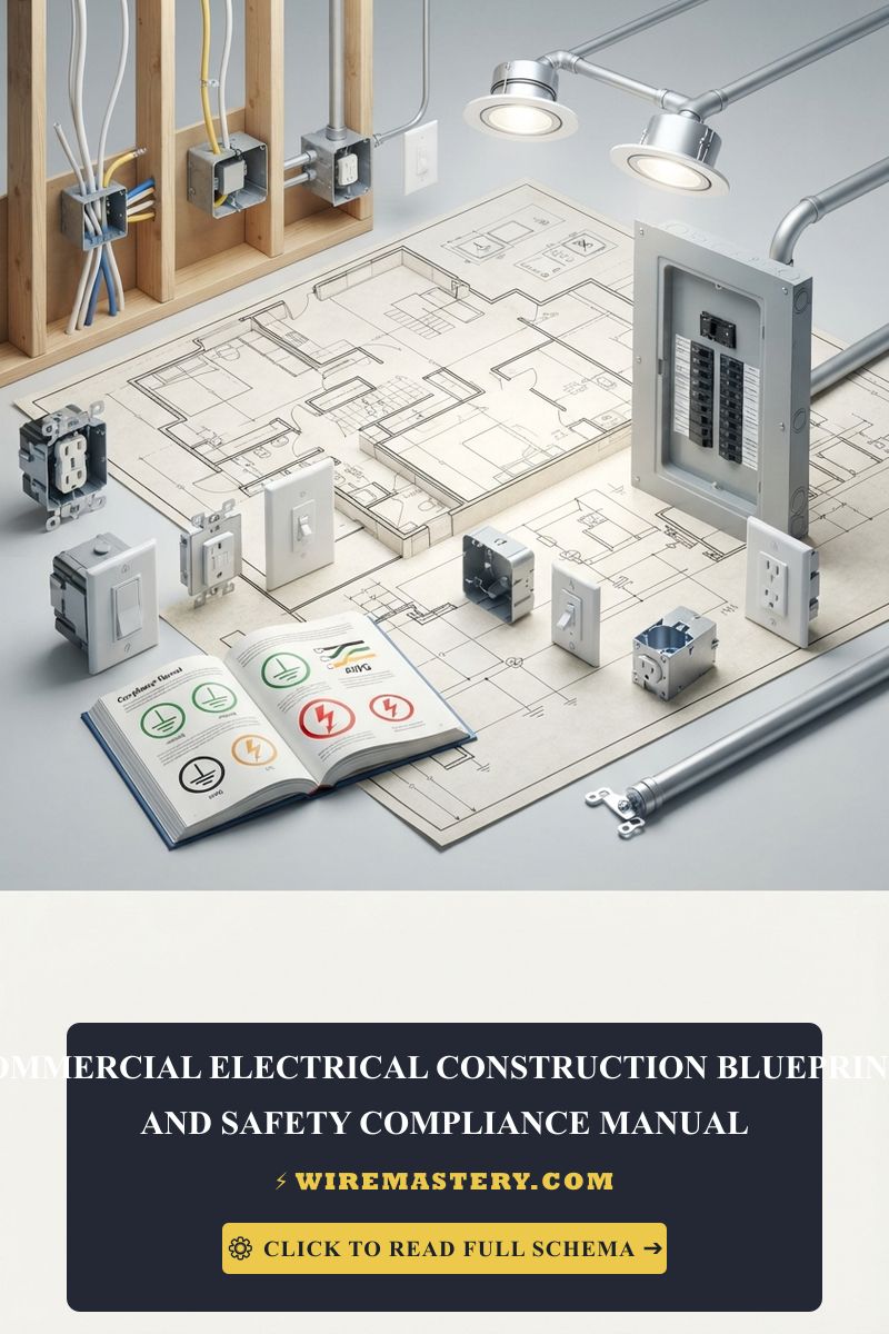
Commercial Electrical Blueprints: Reading One-Line Diagrams
Interpreting high-density commercial electrical construction blueprints, deciphering complex industrial one-line diagrams, and enforcing rigid code-compliant physical installations demands a disciplined command of symbolic nomenclature, spatial raceway calculations, and split-phase power distribution scaling. Within commercial structural frameworks, electrical routing transitions away from flexible, non-metallic residential sheaths to deploy high-capacity Electrical Metallic Tubing (EMT) conduit infrastructures and heavy-gauge stranded conductors. Every phase of a commercial build is governed strictly by the engineering parameters detailed inside the master submittal logs; any installation drift that deviates from the stamped schematics or compromises spatial enclosure boundaries will result in an immediate regulatory project shutdown by the local building code enforcement inspectors.
To guarantee absolute system coordination across multi-phase distribution networks, field operators must cross-reference their layout routings directly against automated electromechanical power contactor control circuits and certified master electrical panel load balancing calculation sheets.
This reference manual despatches the fundamental processes required to translate commercial construction legends, compute industrial conduit fill capacities, and deploy professional on-site diagnostic metrology toolkits.
Core Commercial Blueprint Sizing Parameters
Before feeding high-capacity wire spools into vertical feeder raceways or opening multi-phase switchgear panels, establish these critical baseline metrics:
- The One-Line Diagram Paradigm: The absolute structural roadmap of a commercial blueprint package. Unlike a floor plan that details physical spatial placement, a one-line diagram uses a simplified single-line schematic format to represent the complete holistic path of electrical distribution—tracking current flow all the way from the high-voltage utility transformer vault down through the main service switchgear, automatic transfer switches, and localized subpanel centers.
- The Commercial Minimum Conductor Floor: Under industrial contractor standards and strict localized code amendments, solid copper wires smaller than #12 AWG are completely prohibited for commercial branch circuit power runs, neutralizing structural line resistance across large physical commercial building footprints.
- The 40% Conduit Fill Constraint (NEC Chapter 9, Table 1): When routing multiple current-carrying conductors through a continuous run of Electrical Metallic Tubing (EMT), the cumulative cross-sectional area of all wires combined must never exceed 40% of the internal cross-sectional area of the conduit tubing. Crowding a pipe past this threshold chokes internal ventilation headroom, causing wires to overheat.
Technical Materials & Commercial Site Commissioning Toolkit
Safely interpreting scale metrics and executing micro-ohmic contact diagnostics inside high-voltage switchgear gutters requires specialized testing instrumentation and 1000V-rated insulated tools:
| Industrial Blueprint Tool | Primary Engineering Purpose & Safety Validation Metric |
|---|---|
| True RMS CAT IV Clamp Meter | Category CAT IV 600V certified to safely capture live multi-phase current draws. |
| Architectural Scale Ruler | Calibrated multi-faceted ruler to calculate physical conduit linear runs straight from paper blueprints. |
| Digital Earth Ground Tester | Verifies heavy industrial machinery grounding networks meet strict low-impedance earth bounds. |
| Dual-Phase Non-Contact Tester | Proximity sensor calibrated to identify active electromagnetic fields before skin contact. |
| 1000V Insulated Torque Wrench | Precision instrument to torque heavy commercial panel lugs to exact inch-pound engineering specs. |
Industrial Conductor Profiles & Raceway Ampacity Matrices (NEC Table 310.16)
Sizing commercial feeders requires absolute adherence to stranded wire ampacity limitations and ambient temperature correction variables. Commercial installations strictly deploy independent THHN/THWN stranded copper conductors insulated with flame-retardant, heat-resistant nylon jackets:
- #12 AWG Stranded THHN Conductor (20-Amp Commercial Branch): The universal industrial specification for general office receptacle loops and low-density localized convenience outputs.
- #10 AWG Stranded THHN Conductor (30-Amp Motor Branch): Heavy-duty branch profile. Mandatory to supply small commercial exhaust fans, automated climate systems, and localized dedicated power machinery.
- 2/0 AWG through 500 kcmil Stranded Copper Feeders: Massive, low-resistance industrial conductor lines reserved for routing primary power from the main service switchgear over to localized step-down transformer cabinets and high-density subpanel centers.
Technical Phase 2: Reading Panel Schedules & Executing EMT Raceway Layouts
To execute a flawless commercial deployment, a field engineer must seamlessly translate the symbolic data embedded inside blueprint schedules into real-world physical component torque constraints and geometrical raceway calculations.
1. The Engineering Logic of Panel Schedules
A panel schedule is a specialized master table included in a commercial blueprint package that indexes the exact electrical loading profile of a distribution center. Instead of forcing a technician to guess circuit layouts from a floor plan, the schedule defines:
- The Phase Allocation Layout: Splits the circuit breakers alternatingly across Phase A, Phase B, and Phase C to guarantee an even load balance across the three-phase 120V/208V or 277V/480V utility supply bus bars.
- The Overcurrent Protective Spec: Stamped breaker ratings (e.g., Bolt-On 20A single-pole or 50A 3-pole switches) and their specific targeted downstream hardware assets (such as office receptacle networks or motor compressors).
- The Target Circuit Load Value: Calculated Volt-Ampere (VA) limits assigned to each circuit line, allowing technicians to verify continuous capacity thresholds before landing wire terminations.
2. Geometrical EMT Conduit Bending Calculations (NEC Article 358)
Commercial field crews must route independent THHN stranded wires through rigid Electrical Metallic Tubing (EMT) conduit tracks. Bending these metal pipes to clear structural columns requires applying strict geometric multipliers to prevent conduit flattening:
- The 30° Offset Bend Protocol: To lift a conduit track over a 4-inch concrete wall obstacle, an installer executes two matching 30° bends in opposing directions. Under trigonometry standards, a 30° angle carries a multiplier of 2.0. Multiplying the obstacle height by the constant (4 inches × 2.0) dictates marking the pipe exactly 8 inches apart between the bend arrows, ensuring a pristine profile that permits smooth wire pulls.
🛠️ The Multi-Point Grounding Electrode Note: Look closely at the commercial switchgear blueprints displayed across our industrial engineering manuals. Notice that commercial systems operate under intensive short-circuit fault current parameters. Under the mandates of NEC Article 250, you cannot rely on a single grounding rod driven into the dirt. Commercial infrastructures require constructing a comprehensive Grounding Electrode System that bonds the main panel neutral bus bar to structural building steel, a concrete-encased Ufer grounding electrode, and the municipal metallic water main trunk lines simultaneously to guarantee a zero-potential safety threshold.
Troubleshooting Common Commercial Field Failures
- The Three-Phase Motor Chatters and Overheats Instantly Upon Power-Up: This catastrophic behavior indicates an active Single-Phasing dropout fault or an inverted phase rotation sequence. If an installer misreads the one-line diagram legend and terminates the incoming feeder phases out of order (L2-L1-L3 instead of L1-L2-L3), the magnetic vectors invert, forcing the motorized machinery to spin in reverse. Isolate subpanel switches immediately, deploy your phase rotation tester, and re-index the line conductor shanks down to code compliance.
- The Newly Reset Bolt-On Circuit Breakers Trip Randomly During Office Loading: An absolute indicator of Harmonic Neutral Overheating caused by non-linear loads. Modern commercial office hubs packed with high-density computer networks, solid-state LED luminaire ballast drivers, and variable-frequency motors generate severe harmonic frequencies that distort standard AC waveforms. These frequencies stack up on the shared neutral bus bar rather than canceling out, causing the neutral to carry up to 173% of active phase currents. Upscale your raceways to house down-rated independent neutrals for each phase branch to clear the fault.
- The City Inspector Flags a “360-Degree Bend Limitation” Violation: Under the mandates of NEC 358.26, a continuous conduit run between accessible pull boxes must not contain more than four 90° bends (totaling 360° overall). Forcing wires through a pipe loop containing five or six bends creates extreme friction that shears the nylon THHN insulation jackets inside the conduit track. Cut the pipe segment open and install a code-compliant intermediate junction pull box box to clear the flag.
National Electrical Code Commercial System Regulations
Adhering to strict national installation codes protects your industrial assets, ensures full trade legitimacy, and shields your business from catastrophic legal liabilities. Commercial installations and blueprint routing layouts are heavily cross-regulated under NEC Article 358 (Electrical Metallic Tubing: Type EMT) and Article 408 (Switchboards and Panelboards):
- Secure Conduit Support Directives (NEC 358.30): EMT conduit tracks must be securely fastened and supported mechanically at least once every 10 feet (3.0 meters) along continuous structural runs, and within a tight physical radius of 3 feet (36 inches) of each conduit termination couplings, junction box cavity, or panel entry mouth to prevent mechanical pipeline joint separation.
- The Ready Accessibility Mandate (NEC 408.18): All commercial switchgear components, subpanel gutters, and intermediate overcurrent disconnect handles must be readily accessible and situated where maintenance personnel maintain a clear workspace envelope of 3 feet of front depth clearance under NEC 110.26 rules, fully blocking the storage of commercial cargo or chemical pallets adjacent to bus bar frames.
For the NFPA 70 provisions relevant to this guide on Commercial Electrical Blueprints: Reading One-Line Diagrams, consult the Official NFPA 70: National Electrical Code (NEC).
Conclusion
This article explains commercial electrical construction blueprints, auditing multi-phase load profiles via panel schedules, and executing precise geometrical EMT conduit bending layouts transforms complex industrial projects into highly predictable, electrical operations. By keeping conductor cross-sections fully aligned with NEC Article 310.16 overcurrent limits, enforcing strict 40% conduit fill volumetric limits inside metallic raceways, and respecting mandatory line-of-sight safety workspace clearance parameters, you construct an unshakeable, resilient commercial grid infrastructure. For final checks, complete panel breaker power isolation safety checkups before opening electrical gutters, deploy CAT IV certified digital clamp meters, and execute every terminal step with safety-first precision.







