Electromechanical Systems: Power Relay & Contactor Integration
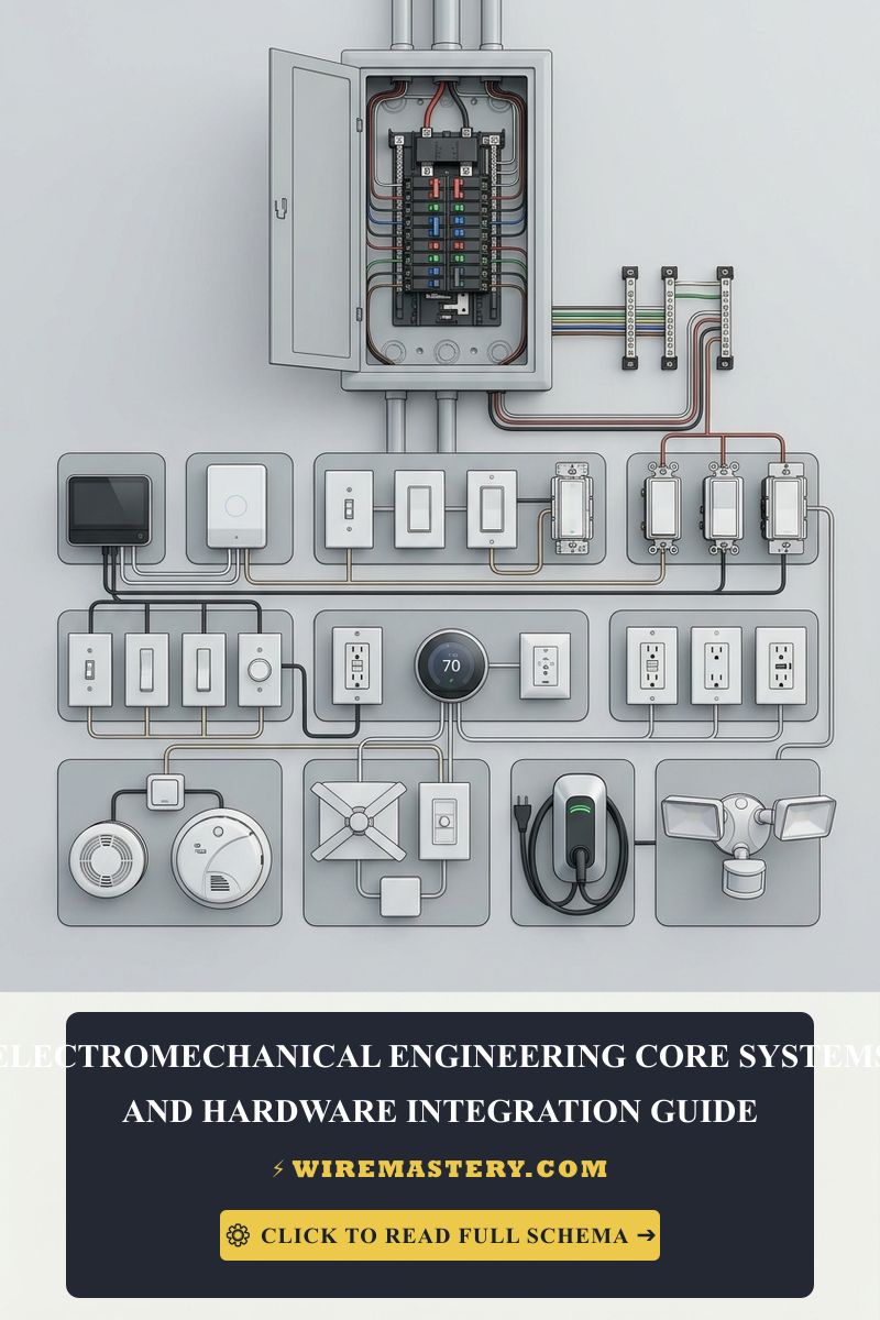
Engineering a reliable, home automation framework or interfacing low-voltage digital processing units with high-amperage continuous line-voltage loads demands a disciplined operational mastery of electromagnetic induction, galvanic isolation boundaries, and solid-state coil switching dynamics. Electromechanical systems embedded within premium modern residences—such as variable-frequency HVAC blowers, automated pool pump matrices, and high-torque automated security gates—rely on an intermediate translation layer to bridge micro-electronic processing logic with high-power grids. When a low-voltage microcontroller (3.3V or 5V DC) triggers a continuous high-load motor line (120V or 240V AC), executing the hardware integration poorly introduces dangerous electromagnetic interference (EMI) noise and volatile counter-electromotive force surges. Bypassing core isolation guidelines will instantly fry logic boards and score contact pads behind finished wall channels.
This engineering manual outlines the physical mechanics of inductive kickback suppression, terminal configurations for heavy-duty contactors, and advanced laboratory waveform diagnostics.
Core Electromechanical System Parameters
Before layout planning or pinning low-voltage microcontroller interfaces into operational relays, decode these foundational boundaries. Apply them to the Electromechanical Systems: Power Relay & Contactor Integration design described in this guide.
- The Inductive Kickback Phenomenon: When power is cut to an electromechanical relay or contactor coil, the magnetic field collapses instantly. This rapid collapse induces a massive, inverse high-voltage transient spike—known as counter-electromotive force or back-EMF—that shoots backward down the signal line, exceeding hundreds of Volts. Bypassing an integrated flyback clamping diode will instantly punch holes through switching transistors.
- Contactor Chattering Degradation: If the supplying low-voltage transformer experiences an active voltage sag dropping control lines below 21V AC under load, the electromagnetic coil inside a motor contactor loses its physical holding force. The internal springs throw the high-voltage contacts open, voltage stabilizes, the coil re-engages, and the contact pads slam shut again. This high-frequency bouncing cycle (chattering) creates continuous carbon micro-arcing that welds the contacts closed.
- The Inrush Current Current Buffer: Motor-driven electromechanical components exhibit massive starting current surges known as Locked Rotor Amps (LRA). Protection devices and conductor lines must be engineered to withstand this transient surge—frequently 600% higher than running currents—without triggering premature circuit trips.
Technical Materials & High-Frequency Diagnostic Laboratory Toolkit
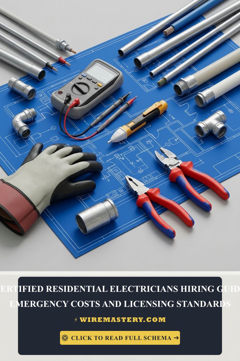
Safely opening high-power control gutters and visualizing logic chattering waveforms requires laboratory-grade diagnostic hardware and protective insulation gear:
| Electromechanical Lab Instrument | Primary Engineering Purpose & Safety Threshold |
|---|---|
| Digital Storage Oscilloscope (DSO) | Minimum 200 MHz bandwidth with low-capacitance active probes to capture transient spikes. |
| True RMS Digital Clamp Meter | Category CAT III 600V certified to safely capture motor startup current spikes. |
| ESD-Safe Temperature Soldering Iron | Precision iron certified under static dissipation guidelines to mount microchips safely. |
| Calibrated Dial Torque Wrench | Ensures mechanical contact terminals are secured to exact inch-pound specifications. |
| Lockout/Tagout (LOTO) Pad Clamps | Universal universal safety devices to mechanically block circuit re-energization during service. |
Conductor Profiles & Motor Branch Load Boundaries (NEC Article 430)
Sizing branch circuits for heavy electromechanical motorized machinery requires strict adherence to conductor cross-sections to prevent house fires. The National Electrical Code strictly regulates motor branch circuits under NEC Article 430 guidelines:
- 14 AWG Solid Copper Conductor (15-Amp Circuit Limit): White sheathing profile. Deployed strictly for low-power control transformers and residential automated valve relays.
- 12 AWG Solid Copper Conductor (20-Amp Circuit Limit): Yellow sheathing profile. The standard structural specification for dedicated general-use convenience loops and low-horsepower fan motors.
- 10 AWG Stranded Copper Conductor (30-Amp Circuit Limit): Orange jacket profile. Required for heavy continuous continuous loads such as residential heat pump compressors and high-tonnage HVAC systems.
Technical Phase 1: Isolating Low-Voltage Logic from Line-Voltage Surges
To successfully integrate a low-power microcontroller (such as an Arduino or ESP32 automation node) to drive a heavy 240V well pump or compressor motor safely, professional automation engineers apply a Three-Tier Galvanic Isolation Topology:
1. Optocoupler Signal Decoupling (The Optical Bridge)
The microchip pins must never connect physically to the copper coils of a line-voltage relay. Instead, the control signal drives an internal infrared LED inside a sealed Optocoupler IC chip. The light shoots across a micro-air gap to activate a photosensitive phototransistor on the opposing side of the substrate. This optical bridge provides an unshakeable barrier that isolates the low-voltage logic plane from up to 5,000V AC transient blowouts occurring down the line.
2. Flyback Clamping Diode Integration (DC Coils Only)
When utilizing a DC-powered intermediate relay to activate a larger AC contactor block, a high-speed 1N4007 Flyback Diode must be soldered in reverse-parallel directly across the relay coil terminals. When the switching transistor turns off, the diode acts as a low-impedance loop that safely traps and dissipates the collapsing magnetic field’s high-voltage energy, protecting the upstream driver chips from back-EMF destruction. For a comprehensive forensic analysis of these micro-scale semiconductor shielding components, follow our master technical manual on transient voltage suppression TVS diode protection circuit standards.
Technical Phase 2: Power Contactor Wiring & Transient Snubber Design
Once your low-voltage control plane is optically isolated from your high-voltage grid components, you must master the physical termination of heavy-duty line-voltage contactor blocks and configure matching hardware filters to absorb high-frequency AC switching arc noise.
1. Step-by-Step Field Blueprint: Wiring an AC Compressor Power Contactor
To configure a professional, code-compliant electromechanical power relay switch to manage a heavy 240V motor load, apply this systematic field installation sequence:
- De-Energize and Isolate Power Loops: Locate your property’s main service subpanel board. Disengage both the dual-pole high-voltage breaker supplying the motor lines and the low-voltage transformer breaker. Install your padlock LOTO safety clamps over both switches. Confirm an absolute 0V state across all terminals using your digital multimeter before handling lines.
- Terminate Line and Load Paths: Insert your incoming 240V line wires from the utility breaker directly into the top pressure plates stamped L1 and L2. Connect the outgoing motor feeder lines directly to the bottom terminal lugs stamped T1 and T2. Use your torque wrench to tighten the lug screws to manufacturer specifications.
- Wire the Low-Voltage Control Coil: Connect your 24V AC signaling lines coming from your optocoupled automation relay board directly onto the small side terminal screws stamped A1 and A2. When the thermostat or microcontroller drops a high logic signal, the 24V current will energize this coil, pulling the mechanical plunger down to bridge L1-to-T1 and L2-to-T2 simultaneously.
2. Designing an RC Snubber Network (AC Coil Protection)
While DC coils utilize simple flyback diodes, switching high-amperage alternating current (AC) loops creates massive physical arcing across contactor points, chewing up metal faces.
- The Technical Remedy: Engineers install an RC Snubber Circuit (a 0.1µF film capacitor wired in series with a 100-Ohm carbon-composition resistor) in parallel directly across the high-voltage contact pads (L1-to-T1). The capacitor acts as a low-impedance high-frequency filter that siphons off the sudden voltage rate-of-rise (dV/dt) spike the exact millisecond the contacts pop open, completely eliminating arc flashes and suppressing electromagnetic interference tracking noise.
🛠️ The BJT Gate Drive Balance Note: Look closely at the solid-state transistor switching schematics displayed across our hardware integration portfolios. Notice that when using a low-power microcontroller pin to drive an intermediate electromechanical relay coil, you cannot attach the microchip pin directly to the transistor base without a current-limiting resistor. Always calculate your gate bias margins; dropping a 1k-Ohm resistor between the microcontroller pin and the base terminal of an NPN BJT transistor saturates the semiconductor channel cleanly, ensuring rapid switching speeds without exceeding microchip milliampere limits. To master these logic level shifts, verify our complete manual on BJT transistor working principles and characteristics.
Troubleshooting Common Electromechanical Failures
- The System Shuts Down and the Control Board Logs a “Sensor Error”: This behavior indicates intense Electromagnetic Interference (EMI) or Cross-Talk noise tracking. If you run fine-gauge low-voltage analog sensor wires parallel to unshielded high-voltage AC motor lines inside the same wall tracks, inductive noise will scramble data streams. Pull the lines and ensure all low-voltage signal paths utilize shielded twisted-pair (STP) category cabling, bonding the foil shield layer exclusively to the system ground plane.
- The Contactor Plunger Chatters and Vibrates Intensely Without Latching: An absolute indicator of voltage starvation or a shorted coil winding. If the upstream 24V control transformer is under-sized or overloaded with too many automated smart hubs, the control voltage will drop below 18V AC the instant the contactor draws current. The spring pushes the plunger back out, voltage rises, and the cycle repeats. Upgrade your HVAC control transformer to a 40 VA minimum rating to clear the fault.
- The Motor Humms Loudly but Refuses to Spin (Locked Rotor): This indicates a single-phasing fault or capacitor collapse. Use your True RMS clamp meter to audit active currents across both L1 and L2 lines. If one leg reads 0 Amps, your disconnect box switch has a burnt contact pad, forcing the motor to stall under inductive strain. Replace the disconnect jaws and test the dual-run capacitor capacitance metrics immediately.
National Electrical Code Motor & Control Circuit Regulations
Adhering to strict national installation codes protects your home automation systems from damage, ensures full trade legitimacy, and shields your business from catastrophic legal liabilities. The National Electrical Code strictly regulates industrial motorized equipment, control safety circuits, and overcurrent protections under NEC Article 430 (Motors, Motor Circuits, and Controllers):
- Motor Disconnecting Means Clearances (NEC 430.102): A dedicated, physical mechanical disconnecting means switch must be installed within clear, un-obstructed line-of-sight of the motor controller and the driven machinery. The maximum structural distance must not exceed 50 feet, ensuring operators can instantly cut line power during an emergency kinetic catastrophe.
- Overload Protection Integration Mandates (NEC 430.32): Continuous-duty motors rated more than 1 horsepower must be equipped with an integrated thermal overload protective relay device to monitor real-time temperature rises, cutting control circuit power automatically before motor winding insulation melts inside the casing tracks.
For current NFPA 70 requirements and relevant IEEE standards covering relay isolation, contactor control, and motor-related wiring, consult the Official NFPA 70: National Electrical Code (NEC) and the Official IEEE Standards Association Database.
Conclusion
This article explains inductive kickback physics, isolating low-voltage digital processing microchips from line-voltage surges using optocoupler optical bridges, and terminating high-amperage contactor blocks with calibrated torque wrench settings transforms complex electromechanical hardware integration into a highly controlled, predictable science. By keeping motor branch conductor gauges fully aligned with NEC Article 430 overcurrent limits, installing parallel RC snubber filters to eliminate high-frequency arcing sparks, and respecting mandatory line-of-sight safety disconnect clearances, you build an exceptionally resilient, safe residential automation ecosystem. For final checks, complete panel breaker power isolation safety protocols before opening electrical gutters, deploy CAT III certified True RMS multimeters, and complete every terminal connection step with precision.