Common Electrical Issues in Older Homes: Legacy Remediation
Introduction
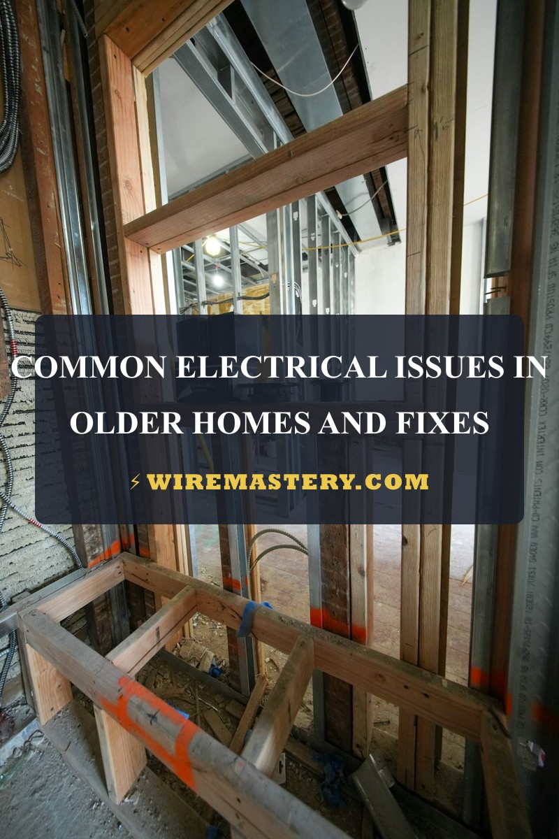
Executing a precise, structural evaluation to isolate and fix common electrical issues in older homes demands a comprehensive operational mastery of historical distribution metallurgies, ungrounded loop topologies, and strict retrofitting compliance codes. Unlike modern residential infrastructures wired with uniform plastic-sheathed copper lines, homes built before the late 1970s house complex, multi-era legacy wiring networks that were fundamentally un-engineered to sustain the intensive continuous current profiles of modern high-density appliance grids. Over extensive duty cycles, ancient asphalt-impregnated cloth insulation wraps crystallize and crumble inside wall tracks, converting structural cavities into volatile fire risks. For property owners integrating smart microgrids, ensuring your historical service lines undergo full diagnostic screening alongside a verified service panel board upgrade load calculation matrix prevents catastrophic structural overloading faults.
This electrical restoration manual outlines the forensic engineering behind knob-and-tube degradation, the thermodynamic physics of vintage aluminum conductor cold-flow failures, and specialized diagnostic laboratory toolkits.
Core Historical Infrastructure Sizing Parameters
Before opening vintage single-gang boxes or executing terminal wire repairs inside cloth-insulated gutters, decode these essential structural boundaries:
- The Knob-and-Tube (K&T) Topology Limit: Deployed widely across North American properties from the 1890s through the 1940s, K&T systems utilize independent, single-conductor copper wires routed through porcelain insulating tubes and anchored onto porcelain knobs. This design lacks an integrated equipment grounding conductor core entirely, possesses a zero-air-space thermal envelope requirement, and must never be covered by modern fiberglass or expanding foam building insulation blankets.
- The Aluminum Series 1350 Hazard: Faced with copper supply constraints in the late 1960s and early 1970s, builders installed solid aluminum conductors (Utility Grade AA-1350) for general 15A and 20A branch loops. This specific alloy suffers from an intense coefficient of thermal expansion, creating rapid creep and cold-flow deformation that slowly backs wire loops out from under standard brass device screws, inducing continuous carbon arcing house fires.
- The NFPA 73 Inspection Metric: Under the strict parameters of NFPA 73 (Standard for Electrical Inspections for Existing Dwellings), an older residential structure must be systematically screened for open splices hidden outside accessible junction boxes, cracked device yokes, and broken neutral return paths before title deed transfers or structural modernizations can occur.
Technical Materials & Legacy Infrastructure Diagnostic Toolkit
Safely tracking ungrounded low-ohmic leakage tracks and auditing vintage cloth-insulated framing studs requires specific category-certified field instruments and protective gear:
| Legacy Diagnostic Instrument | Primary Engineering Purpose & Safety Threshold |
|---|---|
| Digital Storage Megohmmeter | A specialized high-voltage tester (“Megger”) used to verify cloth insulation at 500V DC. |
| True RMS CAT III Multimeter | Category CAT III 600V certified to accurately check baseline ground-fault resistances. |
| Dual-Phase Non-Contact Tester | High-sensitivity tester calibrated to track unshielded live fields through plaster walls. |
| AlumiConn Crimp Tool & Gauge | Specialized ratcheting tool required to execute code-compliant aluminum-to-copper terminations. |
| Class 00 Dielectric Rubber Gloves | Certified high-density rubber wraps rated to block up to 500V AC continuous contact tracks. |
Historical Conductor Profiles & Amperage Load Constraints (NEC 310.16)
When executing an emergency section replacement or re-identifying a vintage wire core to feed an automated smart module, you must match your conductor parameters to the strict mandates of NEC Article 310.16:
- 14 AWG Solid Copper Line (15-Amp Overcurrent Limit): White sheathing or raw cloth wrap. The historical baseline thickness profile for general residential lighting branches.
- 12 AWG Solid Copper Line (20-Amp Overcurrent Limit): Yellow profile or double-braid cloth. Required for kitchen countertop plug zones and high-load utility nodes.
- 12 AWG Solid Aluminum Conductor (15-Amp Maximum Limit): 🚨 Critical Code Adjustment: Under modern building retrofitting standards, if solid branch aluminum wiring of the legacy AA-1350 series is left in service, it must be down-rated and protected via a 15-Amp circuit breaker exclusively, fully blocking its original 20-Amp factory designation to prevent intensive thermal wire breakdown.
Technical Phase 2: Aluminum Repair & No-Ground GFCI Retrofitting
When your insulation resistance audits confirm that the legacy cloth-jacketed system is structurally sound but houses active copper-aluminum mismatch faults, you must execute a code-compliant remediation sequence to secure the building envelope safely.
1. Step-by-Step Field Blueprint: Copper-to-Aluminum Pig-Tailing
Connecting a standard copper pigtail wire straight onto an older solid aluminum wire core using a standard plastic wire nut is a critical fire code violation. The contrasting metals react galvanically, inducing accelerated oxidation and terminal loose play.
- De-Energize and Isolate Power Loops: Locate your property’s main service distribution panel board. Disengage the dedicated circuit breaker supplying power to the target room box. Install your padlock tagout clamps over the switch. Confirm an absolute 0V state across all side terminals using your digital multimeter before handling lines.
- Strip and Prepare Conductor Tips: Strip exactly 1/2 inch of insulation off your solid aluminum conductor core using your wire strippers. Ensure the aluminum surface is free of deep scores or circular gouges.
- Deploy an Approved AlumiConn Connector: Take a certified, UL-listed AlumiConn three-port terminal block module. Insert the raw solid aluminum wire tip into Port 1. Insert a fresh, 6-inch solid copper pigtail wire (#12 AWG or #14 AWG) into Port 2.
- Enforce Precise Torque Controls: Take your calibrated torque screwdriver and tighten the internal steel set screws directly over each wire core to the exact manufacturer specifications printed on the packaging (typically 10 to 15 inch-pounds). The set screw breaks through the aluminum’s surface oxide skin, clamping the metal flat while an internal zinc-based anti-oxidant gel paste seals out oxygen, permanently neutralizing cold-flow oxidation hotspots. Connect the copper tail directly to your new device side screws.
2. Sizing the No-Ground GFCI Safety Loop (NEC 406.4(D)(2))
Older properties constructed before the late 1960s utilize a legacy two-wire infrastructure (one Hot and one Neutral) with zero physical equipment grounding conductor paths inside the cloth sleeves. To upgrade these obsolete two-prong outlets to modern three-prong safety standards legally without tearing out finished plaster walls, professional contractors implement this strict sequence:
- Connect your incoming ungrounded Line Hot wire directly to the brass terminal screw stamped LINE HOT on the rear of a new GFCI receptacle body. Connect your incoming Line Neutral wire directly to the silver screw stamped LINE NEUTRAL. Leave the green grounding hex screw completely empty.
- Paste Mandatory Safety Labels: Take the small adhesive vinyl stickers included inside the factory GFCI retail packaging. Paste the stickers stamped “No Equipment Ground” and “GFCI Protected” directly onto the front face of the plastic faceplate plate.
- The Safety Logic: The internal solid-state current transformer transformer monitors vector balances continuously. Even without a physical grounding wire, if the GFCI senses a micro-ampere current leak siphoning to earth through a user’s flesh, it cuts line power in less than 25 milliseconds, satisfying federal building inspection metrics.
🛠️ The Knob-and-Tube Insulation Hazard Note: Look closely at the building envelope thermal insulation maps displayed throughout our architectural engineering manuals. Notice that vintage Knob-and-Tube (K&T) copper conductors rely on open-air space inside the hollow wall joist cavities to dissipate operational thermal heat. If a home improvement contractor shoves modern fiberglass batting or injects expanding cellulose insulation foam straight into these cavities to upgrade home energy efficiency, the K&T conductors become thermally choked. The wire lines heat up aggressively under standard currents, baking the asphalt cloth jackets into brittle powder and creating an un-mitigated fire hazard inside finished walls.
Troubleshooting Legacy Infrastructure System Failures
- The Breaker Resets Perfectly but Outlets Spark and Sizzle Under Load: This behavior indicates an active aluminum splice creep or loose wire nut arcing fault hidden inside an upstream junction box. The continuous current is jumping across the oxidized gaps of an un-certified aluminum-copper twist connection. Isolate subpanel power immediately, trace your branch lines using a thermal infrared laser scanner, locate the overheating box cavity, and replace the twist connectors with code-compliant torqued AlumiConn terminal blocks.
- The Receptacle Registers 120V on a Voltmeter but Drops to 0V Under Load: An absolute indicator of a High-Resistance Open Neutral or broken splice down the track. The high-impedance multimeter uses zero current, registering a ghost voltage field leaking through capacitive coupling lines. The moment an active appliance is plugged in, the weak, oxidized splice point cannot pass the current draw, and line voltage collapses instantly. Execute a live millivolt drop audit to track down the loose wire nut node.
- Upstream sensitive AFCI Breakers Trip Intermittently Upon Appliance Initialization: This occurs due to crumbly insulation leakage inside legacy boxes. When vintage cloth-jacketed conductors are stuffed tight into cramped single-gang boxes, the brittle insulation cracks and breaks apart, allowing raw hot copper filaments to make micro-contact with the metallic box chassis. Wrap the internal wire shanks thoroughly with two tight layers of high-grade, 600V-rated electrical insulation tape to clear the fault.
National Electrical Code Existing Dwelling Regulations
Adhering to strict national installation codes protects your home investment, maintains property valuation, and ensures full property insurance compliance. Existing residential infrastructures, retrofits, and building modernizations are heavily cross-regulated under NEC Article 406 (Receptacles) and the strict parameters of NFPA 73:
- NFPA 73 Mandatory Correction Flags: The standard dictates that any exposed, un-insulated conductor lines, open splices outside listed boxes, non-grounding outlets substituted illegally with standard three-prong yokes, or any circuit breaker panels displaying visible thermal scorching must be officially logged as a critical safety violation demanding immediate structural remediation before code clearance.
- The CO/ALR Device Requirement (NEC 406.3): If solid aluminum branch wiring is terminated directly to the side screws of convenience receptacles or wall toggle switches without utilizing intermediate copper pigtail links, the hardware devices must carry an explicit factory stamp reading CO/ALR (Copper/Aluminum Revised), certifying the screw alloy is fully engineered to withstand aluminum creep stresses.
For current NFPA 70 and fire-safety guidance on legacy wiring, aluminum conductors, and older-home electrical inspections, consult the Official NFPA 70: National Electrical Code (NEC) and the Official National Fire Protection Association Database. Apply those provisions to the Common Electrical Issues in Older Homes: Legacy Remediation scenario covered in this guide.
Conclusion
This article explains legacy ungrounded loop topologies, executing code-compliant copper-to-aluminum pigtailing using torqued AlumiConn blocks, and resolving three-prong outlet updates through certified no-ground GFCI remediations transforms complex historic building restorations into highly controlled, electrical milestones. By keeping conductor adjustments fully aligned with NEC Article 310.16 limits, erasing dangerous solid aluminum creep shortcuts, and enforcing absolute compliance with NFPA 73 existing dwelling safety metrics, you build an exceptionally resilient, safe residential grid infrastructure. For final checks, complete panel power isolation safety checks before raw line handling, deploy CAT III certified True RMS multimeters, and complete every diagnostic walkthrough step with precision.