Crestron Control System: Programming Basics & Wiring Standards
Engineering a reliable enterprise-grade or luxury residential automation framework requires a profound understanding of deterministic control hardware and low-voltage communication boundaries. Crestron control systems stand as the absolute global benchmark for high-end integrated command hubs, managing multi-room matrix audio/video feeds, digital climate zones, and commercial shading grids simultaneously. Unlike consumer-grade smart devices that rely on volatile Wi-Fi mesh loops, professional industrial automation relies on hardwired, low-impedance bus topologies and custom control logic. However, translating a technical functional layout into a functioning architecture demands absolute precision when tracing serial communication terminals and physical bus power allocations.
This technical manual outlines the core programming architecture logic for Crestron systems, detailed Cresnet bus pinout matrices, and physical field installation standards in full compliance with international communication codes.
Core Automation Control Parameters
Before uploading customized software files or slicing into a high-density multi-conductor control cable, verify these engineering baselines:
- The Cresnet Data Highway: The backbone of standard Crestron hardware ecosystems is the proprietary Cresnet network—a multi-conductor shielded topology that delivers continuous DC power and high-frequency digital signaling loops across hardware nodes.
- The Overcurrent Bus Limitation: A single 3-Series or 4-Series Crestron control processor power supply has strict current limitations (measured in Watts or Amps). Bypassing these power thresholds by overloading too many touchscreens onto a single bus segment will trigger automatic thermal shutdown faults.
- Class 2 Power Isolation Constraints: Crestron control networks operate under Class 2 low-voltage guidelines. Mixing these sensitive differential communication lines with high-voltage 120V/240V building electrical conduits inside the same box enclosure violates national building fire codes.
Technical Materials & Automation Diagnostic Toolkit Checklist
Executing clean, professional low-voltage device terminations and real-time serial tracking requires specific electronics laboratory instrumentation and high-precision trade tools:
| Automation Trade Tool / Material | Primary Engineering Purpose |
|---|---|
| Digital Auto-Ranging Multimeter | Measures exact DC voltage parameters (0V to 30V) and audits differential data line resistances. |
| Precision Terminal Stripper | Calibrated to shear outer PVC jackets clean off 18 AWG and 22 AWG fine stranded conductor cores. |
| Miniature Phoenix Clamping Screwdriver | Flathead jewelers screwdriver designed to torque down tiny wire slots on control block yokes. |
| Digital Storage Oscilloscope | Captures fast digital pulse widths on data lines to diagnose noise contamination dropouts. |
| Dielectric Contact Cleaner Spray | Fast-evaporating compound used to purge carbon residue and oxide scaling off serial ports. |
Decoding the 4-Pin Cresnet Bus Pinout Matrix
To accurately trace physical infrastructure faults across a Crestron control system programming layout, you must ignore generic wiring assumptions and implement the strict international color-code standard assigned to the 4-pin Phoenix terminal connectors.
To evaluate how these low-voltage data highways link up with broader building power lines, review our detailed guide on residential electrical installation standards.
Official Cresnet Conductor Mapping Matrix
| Terminal Pin Pin | Standard Wire Color | Conductor Gauge (AWG) | Core Engineering Role & Schematic Target |
|---|---|---|---|
| 24 | Red | 18 AWG Stranded | +24V DC Power Feed: Delivers operating current from the master processor to accessories. |
| Y | White | 22 AWG Twisted-Pair | Data Plus (Data +): Transmits high-frequency differential digital command signals. |
| Z | Blue | 22 AWG Twisted-Pair | Data Minus (Data -): Transmits high-frequency differential digital command signals. |
| G | Black | 18 AWG Stranded | System Ground (GND): Establishes a common reference return path for power and signaling. |
Advanced Logic Architectures: SIMPL Windows vs. SIMPL# Frameworks
Compiling firmware for a Crestron control processor demands a systematic understanding of deterministic logic flow. Crestron hardware executes custom binaries through two distinct programming layers, depending on systems scale and complexity:
1. SIMPL Windows (The Graphical Logic Engine)
SIMPL (Symbol Intensive Master Programming Language) is the traditional programming foundation used by automation technicians.
- The Logic Structure: Programs are designed graphically using discrete, non-procedural logic symbols such as AND gates, OR gates, Interlocks, and Serial Buffers. Signals propagate through digital inputs, analog levels, and serial text strings.
- Engineering Baseline: Every physical button touch on an automated interface pane triggers a digital transition (0 to 1) that passes through these symbols to execute a specific hardware relay command.
2. SIMPL# and SIMPL# Pro (The Object-Oriented Framework)
For high-density enterprise campuses or complex third-party API integration loops (such as interfacing custom climate sensors or cloud matrix systems), standard logic blocks become inefficient.
- The Logic Structure: Programmers leverage C# (C-Sharp) within the .NET framework Sandbox. This architecture enables object-oriented programming methodologies, multi-threaded execution loops, and custom class libraries to manage data handling seamlessly.
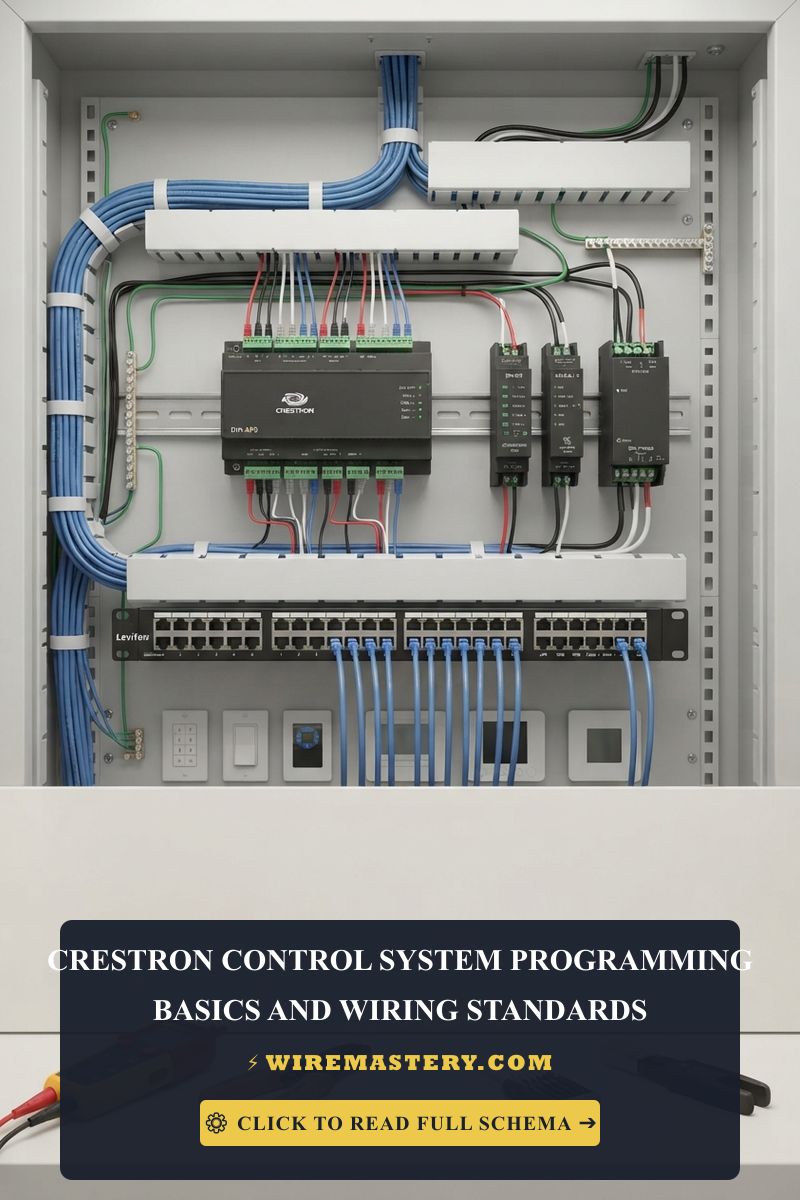
🛠️ Bus Impedance Topology Warning: Look closely at the physical infrastructure layouts displayed throughout your integration manuals. Notice that Crestron communication buses rely on a clean daisy-chain topology. Star wiring configurations or running long, unshielded stubs off the main line creates high-frequency signal reflections that mangle the digital square waves of the differential data pins (Y and Z). Always clamp a 120-Ohm end-of-line resistor across the furthest data nodes if your physical network loop encounters continuous packet dropouts.
Technical Mapping: RS-232, RS-422, and RS-485 Serial Standards
When integrating external equipment (such as video projectors, multi-zone security blocks, or lighting dimming panels) that do not support native Cresnet communication, you must utilize the processor’s built-in COM ports. Tracing these connections on your Crestron control system programming schematic demands strict adherence to official serial pinouts:
Standard RS-232 DB9 Control Port Pinout
| Pin Position | Signal Abbreviation | Direction (Relative to Crestron) | Core Technical Purpose |
|---|---|---|---|
| Pin 2 | RXD | Input | Receive Data: Accepts serial command confirmation codes from the device. |
| Pin 3 | TXD | Output | Transmit Data: Sends ASCII or Hexadecimal control string lines to the hardware. |
| Pin 5 | GND | Neutral | Signal Ground: Establishes the zero-voltage reference loop for signaling data tracks. |
| Pin 7 / 8 | RTS / CTS | Handshaking | Request/Clear to Send: Hardware flow control lines used to prevent data buffer overflows. |
Step-by-Step Field Installation and Bus Commissioning
1. Power Load Sizing Calculation
Prior to stripping any cable jackets, sum the total power consumption factors of all down-stream hardware devices. Crestron accessories specify their power draw using Cresnet Power Units (PUs). For example, a standard 7-inch wall touchscreen might consume 15 PUs. Ensure that the total cumulative PU burden attached to a single processor power supply block does not exceed 80% of its rated capacity limits. If the load is too heavy, you must integrate an external, auxiliary 24V DC power supply module and disconnect the Red (+24V) line from the master processor to isolate power zones.
2. Stripping and Terminating the Phoenix Block
Expose approximately 1.5 inches of the main shielded multi-conductor control cable sheath using your precision strippers. Foil back the static drain shield wire cleanly. Strip exactly 1/4 inch of insulation off the fine stranded 18 AWG power lines (Red/Black) and the 22 AWG twisted-pair data lines (White/Blue). Twist the raw strands tightly, seat them completely inside the corresponding ports of the 4-pin Phoenix plug yoke, and torque the miniature clamping screws down firmly to achieve a low-resistance contact lock.
3. Verification and Live Signal Commissioning
- Set your digital multimeter dial to DC Voltage mode (V_avg).
- Place your black probe onto the Black (GND) terminal pin and your red probe onto the Red (24) terminal pin. Verify the multi-tester reads between +23.8V and +24.2V DC.
- Move the red probe to the Y (Data +) and Z (Data -) pins. The voltage should float rapidly between 1.5V and 3.5V DC, indicating active digital pulse transmission states across the network loop.
Troubleshooting Common Crestron Infrastructure Failures
- Touchscreens Flashing On and Off Intermittently: This behavior indicates an active voltage drop or a severe overcurrent bus overload. If your 18 AWG power wire line extends past 250 feet without an auxiliary power supply, internal copper resistance causes the voltage to drop below the device’s minimum operational threshold. Upsize the power core or inject a localized power module immediately.
- The Processor Communicates with Some Devices but Misses Others: Check for a broken or high-resistance ground loop link or reversed data lines. If you accidentally cross the Y and Z pins on a single downstream terminal block, the differential signaling potential collapses, throwing that specific accessory offline and inducing digital noise dropouts across the remaining network tracks.
- The Serial Control Port Fails to Control the Device: Use an electronics contact spray to clean the DB9 housing pins. Verify your programming configuration settings inside SIMPL Windows match the device’s baud rate, data bits, parity, and stop bits parameter thresholds perfectly. A single mismatch (such as 9600 baud instead of 115200 baud) will mangle the ASCII text string, causing the target hardware to ignore all incoming commands.
National Electrical Code Isolation & Safety Standards
Adhering to strict national structural regulations protects your home automation systems from damage and ensures full insurance compliance. The National Electrical Code strictly regulates commercial automation grids and low-voltage remote-control lines under NEC Article 725 - Remote-Control, Signaling, and Power-Limited Circuits:
- Class 2 Separation Mandates (NEC 725.136): Crestron Cresnet lines operate as Class 2 low-power signaling circuits. The NEC strictly dictates that these unshielded data tracks must maintain a minimum 2-inch clear physical separation from any high-voltage 120V/240V residential power branch lines inside wall cavities, conduits, and equipment rack enclosures unless enclosed in approved metallic conduits. This isolation prevents dangerous line-voltage electromagnetic induction or high-amperage arcing from frying sensitive solid-state semiconductor micro-hardware.
- Plenum and Riser Cable Safety Ratings: Any multi-conductor control cable passing vertically through commercial floors or run horizontally through ceiling plenum air-handling spaces must carry an official safety classification code of CL2P or CL3P to ensure the casing self-extinguishes during a structural fire crisis and does not emit toxic smoke clouds.
For the NFPA 70 provisions relevant to this guide on Crestron Control System: Programming Basics & Wiring Standards, consult the Official NFPA 70: National Electrical Code (NEC).
Conclusion
This article explains Crestron control system programming baselines and enforcing rigid hardwired communication standards transforms complex multi-room automation configurations into robust, infrastructures. By calculating proper PU power load margins, maintaining strict daisy-chain wiring geometries across Cresnet data loops, and respecting mandatory NEC Class 2 separation boundaries inside equipment racks, you build highly resilient, commercial-grade home automation frameworks. Prioritize real-time voltmeter signal testing, eliminate high-frequency bus reflections using proper termination resistance, and design every control loop with systematic precision.