Communication Engineering: Residential Structured Cabling
Engineering a reliable, residential communication network or deploying an unshakeable structured cabling backbone inside automated properties demands an advanced operational understanding of high-frequency attenuation, signal-to-noise ratios (SNR), and strict magnetic field isolation guidelines. Modern smart home automation grids—utilizing 4K/8K video streaming matrix arrays, distributed high-fidelity audio networks, and centralized security processing blocks—can no longer depend on basic, non-shielded wireless data networks to maintain throughput parameters. As signaling frequencies scale into the multi-Gigabit copper spectrum, physical data wires behave as complex transmission lines, rendering traditional low-voltage wiring shortcuts obsolete. To protect sensitive solid-state logic gates from destructive voltage spikes, installers must isolate these networks alongside a verified transient voltage suppression TVS diode protection architecture.
This reference manual outlines the physical mechanics of high-frequency signal propagation, structural Category cable attenuation constraints, and professional electronic laboratory network testing toolkits.
Core Communication Infrastructure Sizing Parameters
Before pulling continuous multi-pair data sheaths through vertical wall studs or terminating high-density patch blocks, decode these essential code thresholds:
- The 10-Gigabit Frequency Floor: Modern structured networking layouts deploy Category 6A (Cat6A) or Category 7 shielded copper lines as the bare minimum infrastructure standard. Operating at transmission frequencies up to 500 MHz, Cat6A copper lines support data transfer rates of 10 Gbps (Gigabits per second) over 100-meter run lengths, requiring tight geometric pairing parameters to sustain signaling integrity.
- The Alien Crosstalk Mitigation Constraint: When multiple high-frequency data cables are bundled together inside a single vertical drywall track, the electromagnetic signals leaking out from individual wire wraps can contaminate adjacent tracks, a fault mode classified as Alien Crosstalk (ANEXT). Suppressing this tracking noise requires utilizing cables wrapped in internal foil shielding loops.
- The 2-Inch Inductive Air Gap Requirement: Low-voltage data signaling tracks are highly susceptible to electromagnetic interference (EMI) cross-talk fields generated by parallel line-voltage building power loops. Under strict building safety codes, communication cables must maintain a physical clearance buffer from all unshielded 120V/240V lines inside wall cavities.
Technical Materials & High-Frequency Network Testing Toolkit Checklist
Safely sorting high-density structural data bundles and verifying multi-gigabit packet transfers requires specialized metrological instrumentation and certified trade hand tools:
| Communication Testing Instrument | Primary Engineering Purpose & Trade Safety Threshold |
|---|---|
| Fluke DSX-8000 CableAnalyzer | Certified field certifier used to audit Cat6A line compliance up to 2 GHz frequencies. |
| High-Precision Optical Power Meter | Measures decibel (dB) insertion loss metrics across localized fiber optic lines. |
| Ratcheting RJ45 Crimp Tool | Compresses shielded modular plug pins uniformly onto solid copper wire pairs. |
| Impact Punch-Down Hand Tool | Seats and shears fine 23 AWG wire conductors into IDC terminal blocks inside patch racks. |
| Visual Fault Locator (VFL) Laser | Injects an intense red laser down fiber lines to pinpoint micro-bends or fracture leaks. |
Conductor Profiles & Data Bandwidth Loading Metrics (ANSI/TIA-568)
When mapping out material specifications for an automated smart home infrastructure network, standard electrical wiring diameters are replaced by specialized communications dimensions. Apply those separation and pathway rules to the Communication Engineering: Residential Structured Cabling setup described here.
- 23 AWG Solid Copper Category 6A Line: The modern gold standard for high-bandwidth home networks. It features thicker solid copper conductors and tighter internal pair twists than older Cat6 variants, eliminating signal attenuation across extensive path runs.
- 24 AWG Stranded Category 6 Patch Cord: Permissible exclusively for short, flexible hookups between the local wall plate port and the consumer device faceplate. Stranded conductors offer high flexibility but exhibit 20% higher signal loss multipliers, making them completely illegal for long structural backbone runs inside drywall cavities.
- OM4 Multi-Mode Fiber Optic Backbone: Deployed to route data between distant subpanel automation cabinets. Utilizing a 50µm laser-optimized core, it supports 100 Gbps speeds, providing absolute immunity against high-voltage panel electromagnetic interference.
Step-by-Step Field Blueprint: Deploying and Terminating a Cat6A Network Backbone
Executing the structural deployment of a residential communications grid requires establishing a centralized distribution node and maintaining tight geometric tolerances across all connection points. Follow this systematic trade sequence to complete the installation safely:
1. Hard Panel Safety and Raceway Routing (NEC 800.133)
Locate the primary central structured media enclosure (typically a recessed flush-mount metal chassis centered in an open utility closet). Route all incoming 23 AWG solid copper Cat6A lines into the enclosure housing through independent plastic conduits, maintaining a strict 2-inch physical separation distance from any high-voltage 120V/240V building power lines running through the same vertical wall studs.
2. Executing the High-Performance T568B Termination Matrix
To eliminate phase-shifting faults and maintain full 10-Gigabit speed parameters across your copper tracks, you must implement the standard T568B color-coding sequence at both the central patch panel and the local wall plate ports:
- Strip exactly 1 inch of the outer PVC protective jacket sheath off the Cat6A cable end using your precision strippers. Avoid nicking the internal conductors.
- Untwist the four wire pairs carefully, ensuring you maintain the internal pair twists up to within 0.5 inches of the final punch-down block contact pins. Backing out twists past this threshold creates an immediate high-frequency data leakage gap.
- Insert the fine solid copper cores into the assigned Insulation Displacement Connector (IDC) slots following the precise T568B wiring architecture:
- Pin 1: White/Orange Stripe
- Pin 2: Solid Orange
- Pin 3: White/Green Stripe
- Pin 4: Solid Blue
- Pin 5: White/Blue Stripe
- Pin 6: Solid Green
- Pin 7: White/Brown Stripe
- Pin 8: Solid Brown
- Use your impact punch-down tool equipped with a sharp cutting blade to jam the conductors into the V-grooves and trim the excess wire tails cleanly. Snapping the shielding drain wire firmly to the metal rack grounding block completes the electromagnetic shielding envelope.
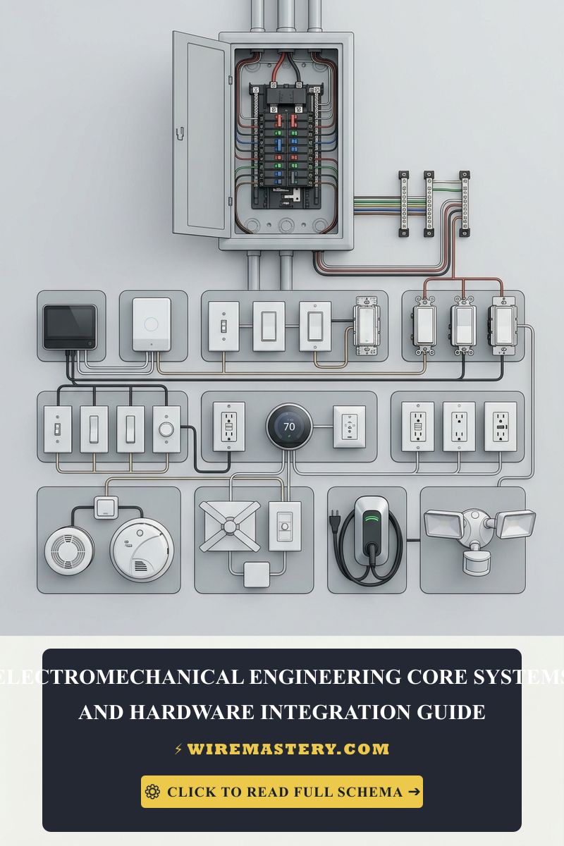
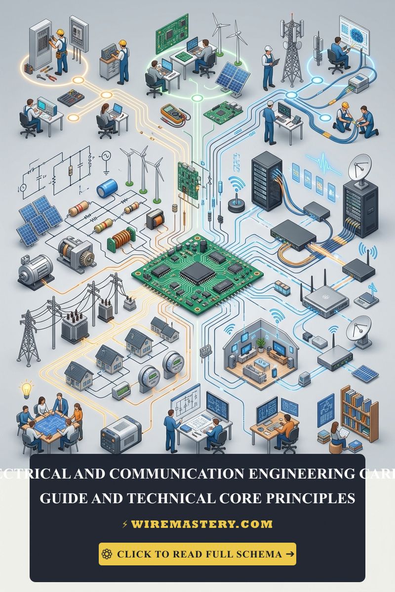
🛠️ The Patch Panel Bending Radius Note: Look closely at the data cabinet infrastructure schematics displayed across our smart automation portfolios. Notice that high-frequency data lines are highly sensitive to physical structural stresses. Under structural cabling guidelines (ANSI/TIA-568), the minimum bending radius for a Category 6A cable must never be less than four times the outside diameter of the cable jacket (typically a 1-inch minimal radius). Kinking or forcing a Cat6A line into a tight 90° angle to stuff it inside a shallow single-gang box will physically alter the internal insulation spacing geometries, inducing intense signal reflections that trigger continuous data packet dropouts.
Troubleshooting Common Residential Communication Failures
- The Connected Device Displays a “No Network Connection” Link Interruption Error: This behavior indicates an active Open Circuit fault or a Crossed-Pair wiring anomaly. Connect your digital cable certifier instrument to the terminal ports; if the screen reports a mapping fault on Pin 3 and Pin 6, you have crossed your green pair wires during the punch-down phase. Re-strip the cable tip and re-terminate the IDC block following the exact T568B color matrices.
- The Network Operates Flawlessly at 1 Gbps but Refuses to Upscale to 10 Gbps: An absolute symptom of Near-End Crosstalk (NEXT) or structural cable distortion. This happens when an installer utilizes cheap unshielded RJ45 plugs or untwists the internal wire pairs past the mandatory 0.5-inch limit during installation. The data packet frames become scrambled by localized inductive cross-talk fields, forcing the network switches to drop speeds down to legacy thresholds to protect data logs. Cut back the tips and re-terminate using premium shielded Cat6A jacks.
- The Smart Automation Display Screen Flickers or Freezes When Large Appliances Start: This indicates severe Electro-Magnetic Interference (EMI) induction tracking. Your low-voltage data cables were routed too close to unshielded 240V HVAC or water heater lines inside the wall framing, violating NEC Article 800 separation boundaries. The massive inrush current from the starting compressor generates a fluctuating magnetic field that corrupts the digital data streams running through the data line. Re-route the low-voltage communication tracks or pull a certified OM4 multi-mode fiber optic line to clear the interference completely.
National Electrical Code Communication Safety Regulations
Adhering to strict national installation codes protects your home automation systems from damage, ensures full property insurance validity, and shields your business from legal liabilities. The National Electrical Code strictly regulates communications circuits and low-voltage structured data drops under NEC Article 800 (Communications Circuits):
- Separation from Power Conductors (NEC 800.133): Communications cables shall not be placed in any raceway, compartment, outlet box, junction box, or similar fitting with conductors of electric light, power, or Class 1 circuits. Data paths entering a shared wall box housing high-voltage switches must be isolated completely behind approved metallic dividers or non-combustible barrier sleeves, preventing line voltage leaks from entering low-voltage logic displays.
- Plenum vs. Riser Insulation Flame Ratings (NEC 800.179): Communication cables routed vertically through hollow floor joists or ventilation air shafts must carry explicit fire safety classifications. Lines traversing vertical floor tracks must be certified as CMR (Riser), while cables routing through active ventilation drop ceilings must carry a CMP (Plenum) rating, incorporating low-smoke fluorinated insulation jackets to prevent toxic gas emissions during a home structural fire emergency.
For current NFPA 70 and IEEE guidance on residential structured cabling, communications pathways, and separation from power wiring, consult the Official NFPA 70: National Electrical Code (NEC) and the Official IEEE Standards Association Database.