Honeywell Thermostat Wiring Diagram: Conventional System Guide
Integrating or retrofitting a modern digital Honeywell Home thermostat into a residential conventional HVAC system is one of the highest-yield home automation upgrades a technician or advanced DIY enthusiast can execute. Unlike complex multi-stage heat pumps that rely on reversing valves to change refrigerant directional paths, a conventional HVAC infrastructure architecture relies on a straightforward, independent dual-engine design: a central gas, oil, or electric furnace for heating loops, coupled with an independent outdoor condensing unit for cooling cycles. However, translating this physical layout into an unshakeable low-voltage control grid demands absolute alignment with standard terminal coding matrices to avoid short-circuiting the system transformer control board.
This technical blueprint outlines the exact wiring diagrams for conventional Honeywell configurations, terminal cross-reference matrices, and low-voltage field safety standards in full compliance with the National Electrical Code (NEC).
Core Structural HVAC Parameters
Before unmounting your existing climate controller or handling low-voltage wires, verify these mechanical baselines:
- The 24V AC Control Constraint: Conventional residential climate control systems in North America operate strictly within a Class 2 low-voltage parameter window (24V AC). Connecting a modern digital thermostat to a high-voltage line system (such as 120V/240V electric baseboard heaters) will instantly cause a severe explosion, melting your smart chip framework and destroying the furnace control board.
- The Power-Stealing Fallacy: While older mechanical mercury switches operated as dry-contact toggles that required zero external power to run, modern Honeywell digital processors feature continuous Wi-Fi radios and LCD backlights that demand a continuous closed current loop back to the transformer.
- System Identification Verification: A conventional system is explicitly defined by having independent heating (W) and cooling (Y) lines running from separate mechanical units. If your outdoor compressor supplies both hot and cold air, you are dealing with a heat pump setup, which requires completely different internal software configuration rules.
Technical Materials & HVAC Diagnostic Toolkit Checklist
Executing a clean, code-compliant low-voltage termination requires specific precision instruments and high-dexterity hand tools:
| HVAC Trade Tool / Material | Primary Engineering Purpose |
|---|---|
| Precision Screwdrivers Set | Miniature flathead and Phillips drivers to secure tiny wire clamps without stripping threads. |
| Solid Wire Strippers | Calibrated specifically to shear outer protective sleeves clean off 18 AWG solid copper cores. |
| Digital Auto-Ranging Multimeter | Measures exact AC voltage outputs (0V to 30V) across the R, C, and signal terminals. |
| Non-Contact AC Tester | Audibly confirms complete power isolation inside the furnace chassis enclosure before trade work. |
| Pocket Level Alignment Tool | Ensures the subbase mounting plate rests perfectly straight for neat faceplate docking. |
The American Wire Gauge (AWG) Thermostat Standard
To prevent high-resistance voltage drops and ensure signal integrity across long structural runs between the living space and the basement utility closet, you must utilize the correct cable profile under NEC constraints:
- 18 AWG Solid Copper (The Trade Standard): Thermostat cable bundles (such as 18/5 or 18/7 sheaths) utilize solid copper cores rather than stranded strands. This solid profile allows the wire tips to slide cleanly into modern push-pad terminal blocks, establishing a low-resistance physical connection.
- Maximum Length Allowances: Standard 18 AWG copper lines maintain perfect 24V signal integrity up to 100 feet of total run distance. If your structural pathways exceed 100 feet from the furnace board to the wall base, you must upsize the control lines to 16 AWG solid copper to mitigate progressive signal voltage sags.
Decoding the Honeywell Conventional Terminal Matrix
To read a Honeywell home thermostat wiring diagram accurately, you must ignore the insulation colors of the house wires and focus exclusively on the letter codes stamped onto the plastic subbase terminal block framework.
To explore how these low-voltage communication paths cross-reference with wider smart grid upgrades, review our master manual on smart thermostat installation guidelines.
Conventional 24V AC Control Terminal Mapping
| Terminal Code | Standard Wire Color | Primary Technical Function & Schematic Target |
|---|---|---|
| R | Red | 24V AC Power Input: The continuous hot feed coming straight from the furnace transformer. |
| RC | Red (Alternative) | 24V AC Cooling Power: Dedicated power input to energize the cooling control relay. |
| W / W1 | White | Heating Stage 1 Relay: Activates the gas valve, oil burner, or electric heating elements. |
| Y / Y1 | Yellow | Cooling Stage 1 Relay: Sends a 24V pilot signal to pull in the outdoor compressor contactor coil. |
| G | Green | Indoor Blower Fan Relay: Energizes the indoor air circulation fan blower motor inside ducts. |
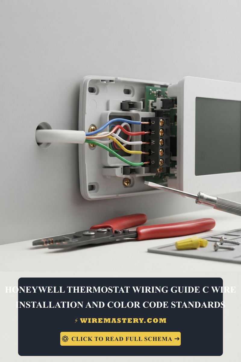
| C | Blue / Black | The Common Return Line: Completes the 24V circuit back to the grounded transformer side. |
Advanced HVAC Engineering: The R-to-RC Jumper Configuration
A major paint-point during conventional system wiring is managing the electrical power feed distribution. Honeywell Home subbase blocks handle heating and cooling currents independently through the R and RC terminals.
Single-Transformer Systems (The Modern Standard)
If your home runs a standard single furnace unit that houses a unified 24V AC transformer supplying both the heating elements and the AC compressor loops, you have a single-transformer system.
- The Blueprint Action: You must install a solid metal slider or a small copper jumper wire connecting R and RC together. This ensures the single incoming hot Red line feeds voltage to both internal control circuits. Modern Honeywell thermostats ship with a built-in R-to-RC slider tab pre-engaged from the factory.
Dual-Transformer Systems (Legacy Infrastructure)
In older properties where a completely separate heating boiler loop coexists with a totally independent add-on central air conditioning air handler, you are dealing with a dual-transformer layout.
- The Blueprint Action: You must physically remove the metal jumper wire or slide the tab to the OPEN position. Connect the Red wire coming from your heating furnace directly to the R / RH terminal, and connect the Red wire coming from your cooling air handler directly to the RC terminal. Leaving the jumper engaged in a dual-transformer setup will connect two independent AC voltage phases together, instantly burning out both transformers in a cloud of toxic smoke.
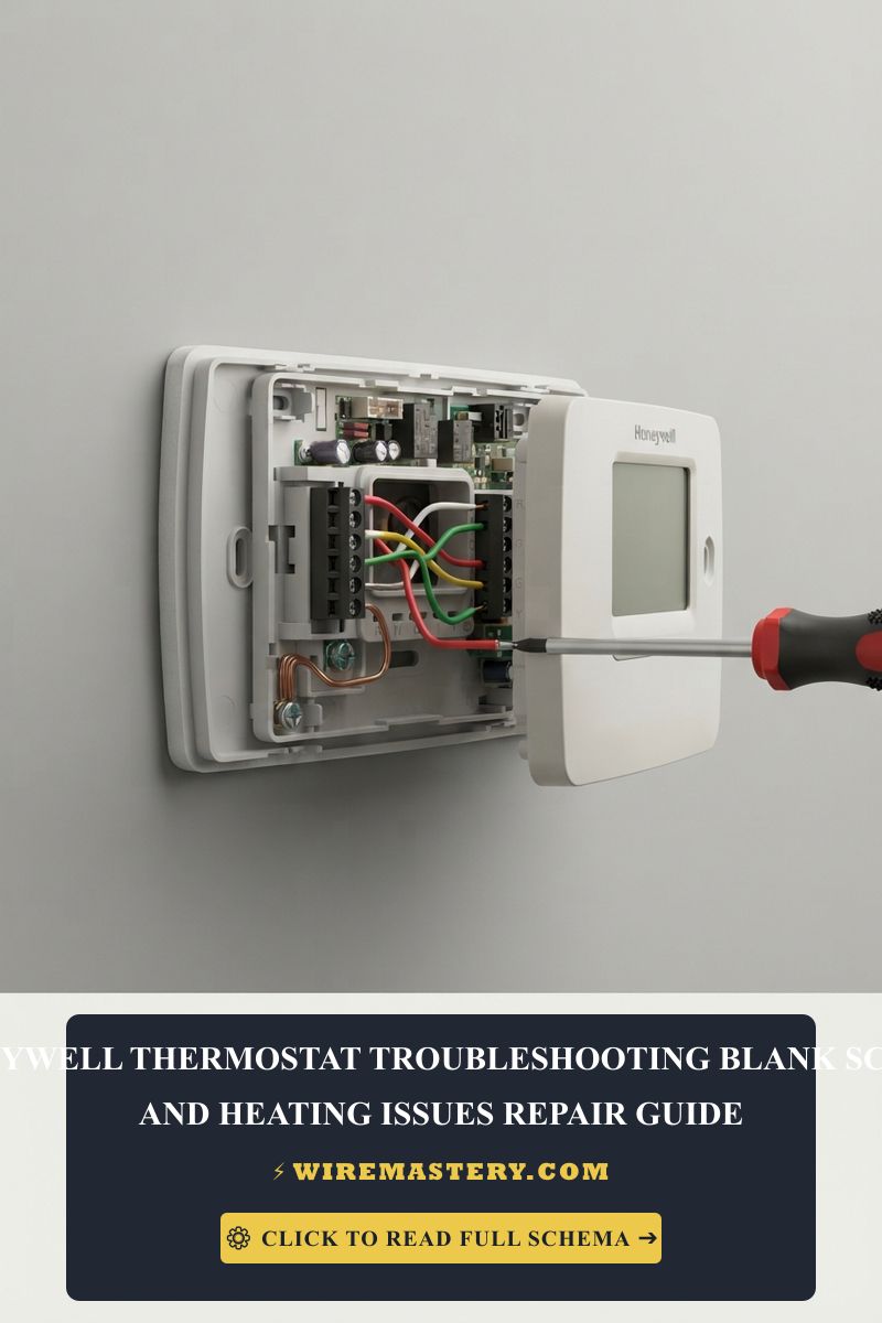
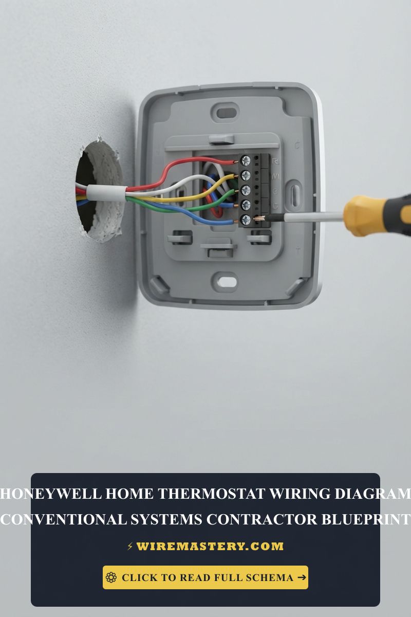
🛠️ Contractor Installation Note: Look closely at the structural cable configurations showcased across your guide assets. Notice how the individual 18 AWG solid copper wire leads are stripped cleanly, leaving no raw copper hairs protruding past the terminal clamping block face. When feeding the main multi-conductor cable sheath through the center wall opening, always pack the drywall cavity behind the subbase plate with fiberglass insulation or electrical putty to stop draft air from trickling out of the wall, which would give your Honeywell sensor false ambient room temperature readings.
Step-by-Step Honeywell Conventional System Wiring Blueprint
1. Pre-Installation Isolation Protocol
Locate your property’s primary breaker panel block. Identify and trip the dedicated circuit breakers powering your heating furnace and your outdoor air conditioner compressor. Go down to the furnace utility closet and turn off the toggle safety switch next to the cabinet housing. Prior to disconnecting a single wire from the old wall subbase, press your non-contact voltage tester against the R line to confirm the circuit reads a complete 0V AC state.
2. Device Extraction and Structural Wire Identification
Remove your old thermostat faceplate. Before backing out any terminal screws, take a clear digital photograph of the wire configurations for reference. Disconnect the conductors one by one, using labeling tape to mark each line based on the terminal letter it was screwed into, never the insulation color. Remove the legacy subbase plate from the wall drywall.
3. Securing and Leveling the Honeywell Subbase
Feed the 18 AWG solid copper wire bundle through the center opening of your new Honeywell Home wall plate. Align the bracket square against the drywall using your pocket level alignment tool. Secure it firmly into position using the provided drywall anchors and mounting screws. If the subbase sits crooked, the internal digital tilt sensors can miscalculate or suffer mechanical drift over long operational cycles.
4. Terminating the 18 AWG Conductors
Straighten your solid copper wire leads using your pliers. Insert the raw copper ends firmly into the corresponding matching terminals based on your tagged labels (Red to R/RC, White to W, Yellow to Y, Green to G, and Blue/Black to C). Tug each wire gently to ensure the internal spring-tabs have locked onto the copper shank. Snap your new Honeywell digital thermostat display faceplate directly onto the base framework.
Troubleshooting Common Conventional Wiring Faults
- The Thermostat Screen Remains Blank: This indicates a complete power loop failure across the R and C lines. First, verify the HVAC cabinet blower door is fully compressed. Conventional furnace doors incorporate an internal mechanical safety interlock switch that cuts all 24V transformer power instantly when the door is opened for filter maintenance.
- The Fan Blows Air but the Outdoor AC Compressor Fails to Start: This behavior indicates a faulty Y cooling stage loop connection. Check the terminal block inside your furnace cabinet; ensure the yellow wire hasn’t slipped out of its terminal screw. If the wiring is secure, use your multimeter to check voltage across Y and C when calling for cooling; if it reads 24V AC, the wiring is fine, and the fault lies in a blown outdoor disconnect box fuse or a dead compressor run capacitor.
- The Furnace Short-Cycles and Cuts Off Early: This occurs when an installer forgets to wire the C (Common) line, forcing the thermostat to cycle in “power-stealing” mode. The smart processor attempts to siphon power through the heating relay coil, triggering premature shutdown cycles across modern electronic furnace control boards. Connect a dedicated C-wire return line to stabilize the current loop.
NEC Code Compliance for Low-Voltage Climate Control
Adhering to strict national structural regulations protects your home insurance coverage and prevents fire hazards inside finished walls. The National Electrical Code strictly regulates residential thermostat wiring networks under NEC Article 725 - Remote-Control, Signaling, and Power-Limited Circuits:
- Class 2 Circuit Isolation Requirements: Thermostat wire arrays operate as low-voltage Class 2 signal lines. The NEC strictly dictates that these unshielded control lines must maintain a minimum 2-inch clear physical separation from any high-voltage 120V/240V branch power circuits inside wall cavities and enclosure boxes unless enclosed in approved conduits. This isolation prevents high-voltage inductive arcing from crossing into low-voltage digital hardware networks.
- Fire Jacket Material Safety Ratings: Thermostat cable bundles passing vertically through residential walls or structural floors must carry a minimum safety rating of CL2 or CL3 (Class 2/3 General Purpose) to ensure the outer PVC jacket self-extinguishes during a structural fire emergency and does not emit dense toxic smoke tracks.
For the NFPA 70 provisions relevant to this guide on Honeywell Thermostat Wiring Diagram: Conventional System Guide, consult the Official NFPA 70: National Electrical Code (NEC).
Conclusion
This article explains a Honeywell thermostat wiring diagram and execution rules upgrades your property’s infrastructure durability and ensures optimized energy efficiency across your residential conventional HVAC grid. By enforcing correct R-to-RC jumper slide configurations, securing solid 18 AWG copper terminations, and respecting mandatory NEC Class 2 separation boundaries inside walls, you construct an expert, home environment. For final checks, complete furnace breaker power isolation testing, utilize certified auto-ranging multimeters, and wire every phase with code-compliant precision.