Smart Thermostat Installation Guide: Easy DIY (Nest, Ecobee & C-Wire)
Introduction
Smart thermostats offer homeowners enhanced control over their heating and cooling systems, optimizing energy usage and saving on utility bills. Installing one is a project you can easily tackle without professional help. This comprehensive manual provides the essential technical know-how, low-voltage safety parameters, and wire configurations required to complete your upgrade safely, including how to bypass a missing common wire.
Before mounting any digital climate hardware, verifying the gauge of your low-voltage power lines is essential. Modern smart thermostats rely on steady, solid-conductor currents. Mastering the fundamentals outlined in a comprehensive electrical wire size gauge chart ensures your residential wiring setup meets the safety ampacity and dimensions required for home automation integration.
Key Technical Specifications Checklist
Before handling your low-voltage HVAC control lines, verify your structural parameters:
- Circuit Voltage: Strictly 24V AC (Alternating Current). Never connect a smart thermostat to high-voltage line voltage systems (120V/240V electric baseboard heaters).
- Conductor Dimension: Must utilize 18 AWG solid copper wire (standard thermostat wire bundles like 18/5 or 18/7). Using thin 20 AWG wires for runs extending past 100 feet will create an intense low-voltage drop.
- System Type: Identify if your home runs a standard forced-air gas furnace or a modern heat pump system with reversing valve controls.
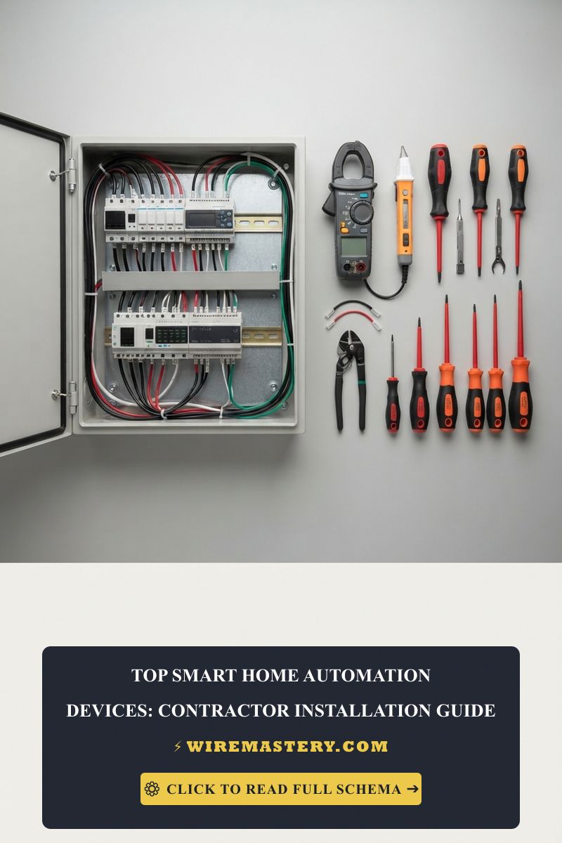
Technical Materials & Low-Voltage Control Diagnostics Toolkit
Executing a clean trade installation requires specific diagnostic instrumentation and insulated trade hand tools:
| HVAC Automation Tool | Primary Engineering Purpose & Safety Threshold |
|---|---|
| True RMS Digital Multimeter | Measures low AC voltage scales accurately without loading down sensitive logic tracks. |
| Non-Contact AC Voltage Tester | High-sensitivity tester calibrated to detect both 120V line power and 24V control loops. |
| Precision Terminal Wire Stripper | Calibrated to cleanly remove PVC insulation jackets off delicate 18 AWG solid wire cores. |
| Magnetic HVAC Wire Labels | High-visibility vinyl markers to index terminal wires before uncoupling hardware blocks. |
| Cushion-Grip Jewelers Drivers | Miniature flathead drivers engineered to secure fine-gauge terminal block screws without stripping. |
Advanced HVAC Engineering: The Mechanics of the C-Wire
The absolute foundation of any modern smart thermostat installation is the blue Common wire (C-wire). Traditional mechanical thermostats operated as simple dry-contact switches that required no external power to run. However, modern smart devices feature continuous background Wi-Fi syncing, color touchscreens, and smartphone radios that demand a steady current loop.
The C-wire does not carry power to the device; instead, it completes the low-voltage electrical circuit back to the HVAC system’s 24V transformer.
- Without a C-Wire: The thermostat will attempt “power stealing” from the heating or cooling circuits (W or Y lines), which causes modern furnace control boards to chatter, short-cycle, or blow a fuse.
- With a Dedicated C-Wire: Your smart chip receives clean, isolated, continuous power distribution 24/7, maximizing hardware longevity.
Official US Thermostat Wire Color Code Standards
To prevent short circuits on your furnace control board, you must map your solid copper wires to their corresponding letters on the wall subbase plate. Standard residential HVAC installations in the United States follow specific industry color conventions under national standards:
| Terminal Letter | Standard Wire Color | Primary Technical Function |
|---|---|---|
| R / RC / RH | Red | 24V AC Power: Continuous hot feed from the transformer. |
| C | Blue / Black | Common: Completes the 24V loop back to the transformer. |
| W / W1 | White | Heat Stage 1: Controls the gas furnace or heating elements. |
| Y / Y1 | Yellow | Cooling Stage 1: Activates the outdoor compressor contactor. |
| G | Green | Indoor Blower Fan: Manages the indoor air circulation fan. |
When retrofitting solid-state digital climate hubs inside older properties constructed before standard wiring compliance, developers regularly encounter boxes lacking an explicit common path. Cross-reference your field setup options directly with our comprehensive manual on no-neutral smart switch wiring insulation and home automation devices to stabilize your logic power lines without creating ground-loop leakage paths.
Solving a Missing C-Wire: PEK Kits and External Transformers
If your wall box lacks a true Common wire core, you can implement one of these two professional bypass methods instead of pulling new cables through finished drywall:
Method 1: Integrating an Ecobee Power Extender Kit (PEK)
When your wall layout houses only four wires (R, G, Y, W), a professional contractor deploys a 5-to-4 wire multiplexing module directly at the furnace control board enclosure:
- De-energize the system: Toggle the furnace breaker to “OFF” and open the blower panel door to break the safety interlock switch loop. Confirm 0V AC with your multimeter between R and C.
- Disconnect lines: Disconnect the G (Green) and Y (Yellow) lines from the furnace main terminal strip.
- PEK input connections: Connect the four incoming thermostat wall conductors directly into the matching terminal slots on the input side of the PEK module.
- PEK output wires: Anchor the five pre-terminated wire leads extending out from the PEK assembly onto the furnace main board block matching their designations: R to R, C to C, G to G, Y to Y, and W to W.
- This architecture uses an integrated diode steering network to multiplex the fan and cooling signals safely down the remaining copper lines, freeing up one core to act as a continuous Common (C) return path.
Method 2: Installing an External 24V AC Isolation Transformer
When retrofitting an advanced smart thermostat onto an older, dedicated two-wire hydronic boiler heating loop (R and W), a PEK cannot be deployed. You must inject localized voltage using an external UL-listed Class 2 isolation transformer plugged into a nearby receptacle:
- Route an 18 AWG solid copper dual-conductor thermostat cable from the plug-in transformer into the thermostat wall box cavity.
- Connect the two original boiler lines directly to the W (Heat) and Rh (Heat Power) terminals on the smart thermostat backplate base.
- Take the two fresh conductor leads coming from the external 24V AC transformer. Insert one lead directly into the C (Common) terminal slot and insert the second lead into the Rc (Cool Power) terminal slot.
- Modern smart thermostats feature smart internal micro-relays that automatically separate power zones when they detect independent lines inside both ports. This isolates the boiler’s delicate switching circuit from the external transformer’s voltage loop, allowing the thermostat to charge continuously through the Rc-to-C loop.
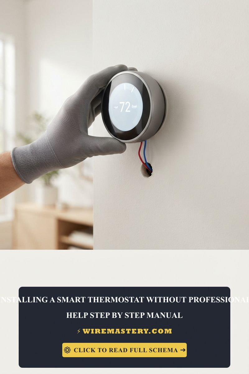
Step-by-Step Smart Thermostat Installation Manual
1. Power Isolation and Voltage Testing
Locate your property’s main service panel or the dedicated switch next to your furnace. Disengage the circuit breaker powering your heating and cooling equipment. Prior to loosening any screws on the old wall plate, use a tester across the R and C wires to confirm the lines register 0V AC before proceeding.
2. Disconnecting and Labeling the Old Hardware
Remove the old thermostat faceplate. Before disconnecting a single conductor, take a clear digital photograph of the layout for reference. Label each wire with flags or tape based on the terminal letter it was screwed into, not the wire color. Remove the old subbase plate carefully.
3. Mounting and Leveling the New Subbase
Feed the 18 AWG wire bundle through the center opening of your new smart thermostat wall plate. Use your alignment level to ensure the bracket sits completely straight. Secure it flush against the wall drywall using the provided mounting screws and anchors.
4. Terminating the 18 AWG Conductors
Straighten your solid copper wire leads. Push them firmly into the corresponding matching terminals (R to R, C to C, W to W, Y to Y, G to G). Ensure no bare copper strands bridge adjacent ports, as touching R to C will instantly pop the 3-amp blade fuse located inside your furnace chassis. Snap the thermostat display faceplate onto the base.
Troubleshooting Smart Thermostat Installation Pitfalls
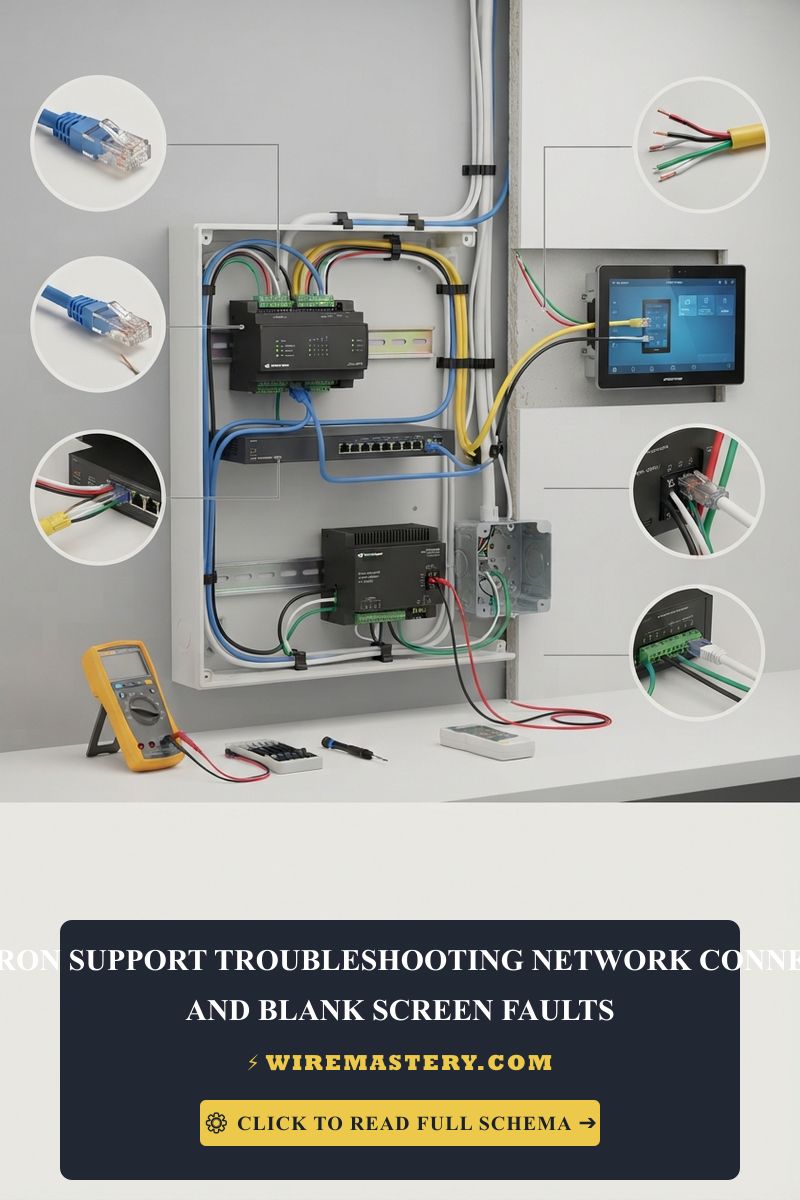
- The Thermostat Screen Remains Blank: Verify the HVAC cabinet door switch is fully compressed. Furnace blower doors feature safety interlocks that cut all 24V transformer power when opened. If the screen stays dark, check the internal 3-Amp or 5-Amp automotive blade fuse mounted directly on the furnace control board faceplate.
- The Thermostat Frequently Drops Its Wi-Fi Connection: An absolute symptom of intermittent current choking. If you install a power-stealing smart device on a system without a true Common (C) wire, the device can only siphon power while the system is off. During long heating cycles in deep winter, the thermostat stays bridged continuously, forcing a network dropout. Install a true C-wire adapter or an external isolation transformer immediately.
- System Blows Cool Air During Heating Cycles: This indicates a crossed wire between your W and Y loops, or an unconfigured heat pump reversing valve setting within your smart software configuration app.
NEC Compliance & Official Safety Standards
Adhering to official structural codes ensures your low-voltage installations are completely safe. The National Electrical Code strictly regulates Class 2 remote-control, signaling, and power-limited circuits under NEC Article 725.
- Class 2 Power Source Safety Limitations (NEC 725.121): All low-voltage smart thermostat control networks must be supplied exclusively by a certified Class 2 power source (such as a current-limited 24V HVAC transformer). Total power output is constitutionally limited to a level that cannot induce electrical arcing or spark structural fire hazards behind finished walls.
- Separation of Circuits inside Junction Boxes (NEC 725.136): Class 2 low-voltage thermostat conductor cables are strictly prohibited from occupying the same conduit tracks, raceways, or structural wall enclosure boxes with high-voltage 120V/240V building power lines unless separated by an approved metallic partition.
For current NFPA 70 guidance on 24V HVAC control circuits, thermostat wiring, and separation from line-voltage conductors, consult the Official NFPA 70: National Electrical Code (NEC).
Conclusion
This guide covers executing a smart thermostat installation without professional assistance steps up your home’s energy efficiency envelope and refines your home automation ecosystem. By tracking your terminal letters, checking your 18 AWG solid copper connections, implementing PEK diode arrays or external transformers where needed, and respecting NEC safety guidelines, you build a safer, smarter home grid environment. Prioritize safety, verify voltage states, and enjoy your modern climate control setup.