How to Test a Circuit Breaker with a Multimeter Safely
Executing a precise, technical audit to test a residential thermal-magnetic circuit breaker inside an energized service panel box demands a disciplined understanding of internal contact resistance, millivolt line sags, and structural fault pathways. While an overcurrent breaker that handles baseline currents might appear operationally sound based on a simple visual inspection, internal mechanical degradation—such as pitted silver contact pads or a weakened internal latch spring—typically manifests through excessive local resistance. When a high-amperage continuous load draws current through an oxidized internal breaker junction, it converts electrical energy into intense localized thermal heat, causing the breaker casing line to trip prematurely. For properties driving heavy appliances, isolating these diagnostic sweeps alongside a verified tankless water heater installation layout ensures primary feeder bus bars are not operating under destructive temperature parameters.
This reference manual outlines the precise mechanical definitions of contact resistance, live millivolt drop calculation matrices, and advanced electronic laboratory diagnostic toolkits.
Core Breaker Diagnostics Parameters
Before removing deadfront distribution guards or touching multi-tester probes to energized terminal screws, decode these foundational boundaries:
- The Closed-Contact Resistance Threshold: A healthy, code-compliant residential circuit breaker operating in the full “ON” position should exhibit an internal electrical resistance baseline approaching 0 Ohms. When using high-accuracy low-resistance ohmmeter scales, a pristine contact set typically registers less than 0.05 Ohms (0.05 Ω).
- The Millivolt Drop Limitation: When auditing a breaker under live, continuous branch circuit loads, the total voltage drop directly across the internal contacts (measured from the live bus bar clip to the wire terminal screw lug) must stay strictly below 100 millivolts (100 mV AC) under full loading thresholds. Any reading exceeding this parameter confirms internal terminal pitting.
- The CAT Safety Rating Prerequisite: Main service entrance panel boards are highly volatile zones exposed to massive transient energy spikes. Technicians must strictly utilize digital multimeters independently certified for Category III (CAT III 600V/1000V) or Category IV (CAT IV 600V) operation to prevent hardware blast housing failure.
Technical Materials & High-Energy Panel Board Testing Toolkit
Safely backing out enclosure deadfront panels and isolating low-resistance micro-ampere fields requires specific certified insulated tools and testing instrumentation:
| Electrical Auditing Instrument | Primary Engineering Purpose & Safety Threshold |
|---|---|
| True RMS CAT III Multimeter | Must feature high-resolution Millivolt (mV) and low-Ohm (Ω) diagnostic scales. |
| Digital Infrared Laser Thermometer | Non-contact thermal scanner used to isolate localized hot breaker casings from a safe distance. |
| Insulated Square-Drive Driver | Cushioned 1000V-rated driver to safely back out deadfront and terminal lug panel screws. |
| Class 00 Dielectric Rubber Gloves | Certified high-density rubber wraps rated to block up to 500V AC continuous contact tracks. |
| ANSI Z87.1+ Safety Goggles | High-impact polycarbonate lenses protecting eyes from sudden arc-fault copper splatter. |
Conductor Diameters & Terminal Torque Specifications (NEC 110.14)
When terminating or replacing a circuit breaker that failed your multimeter audit, you must match your solid copper conductor gauges directly to the overcurrent limit in strict compliance with NEC Article 310.16:
- 15-Amp Overcurrent Breaker: Paired exclusively with a minimum of #14 AWG solid copper conductors. Standard white insulation sleeve; common across residential lighting runs and bedroom receptacle loops.
- 20-Amp Overcurrent Breaker: Paired exclusively with a minimum of #12 AWG solid copper conductors. Standard yellow insulation sleeve; mandatory for kitchen small appliance branch circuits (SABC).
- The Mechanical Torque Requirement (NEC 110.14(D)): Loose conductor wire ends inside a breaker terminal pressure plate create localized resistance, mimicking an internal breaker failure. Installer teams must deploy a calibrated torque screwdriver to secure breaker lugs tightly to exact manufacturer specifications stamped on the device mold (typically 35 to 45 inch-pounds).
Technical Phase 1: The Safe Unpowered Closed-Contact Continuity Test
To verify if an overcurrent breaker has suffered severe internal mechanical arc damage or carbon scaling without working around dangerous live bus bars, apply this unpowered diagnostic routine:
1. Hard Panel Power Isolation & Extraction
Go to the top of your master distribution box panel. Locate the massive Main Disconnect Breaker (150A/200A switch) and toggle it to the full “OFF” position. Install your padlock LOTO safety clamp device over the handle to block accidental re-activation. Remove the panel sheet-metal deadfront cover carefully. Use your non-contact tester to confirm an absolute 0V AC state across the entire workspace area. Use your panel puller pliers to un-snap the target breaker off the live bus bar tab entirely, pulling it forward away from the panel chassis.
2. Setting Up the Multimeter for Resistance Tracking
Take your digital multimeter and rotate the dial to the Continuity setting (indicated by an audible Speaker/Beeper or Ohms Ω symbol). Short your black and red testing probes together directly; the meter must emit a continuous loud beep and display a resistance reading close to 0.0 Ω, confirming your test leads are functional.
3. Measuring the Internal Contact Loop Resistance
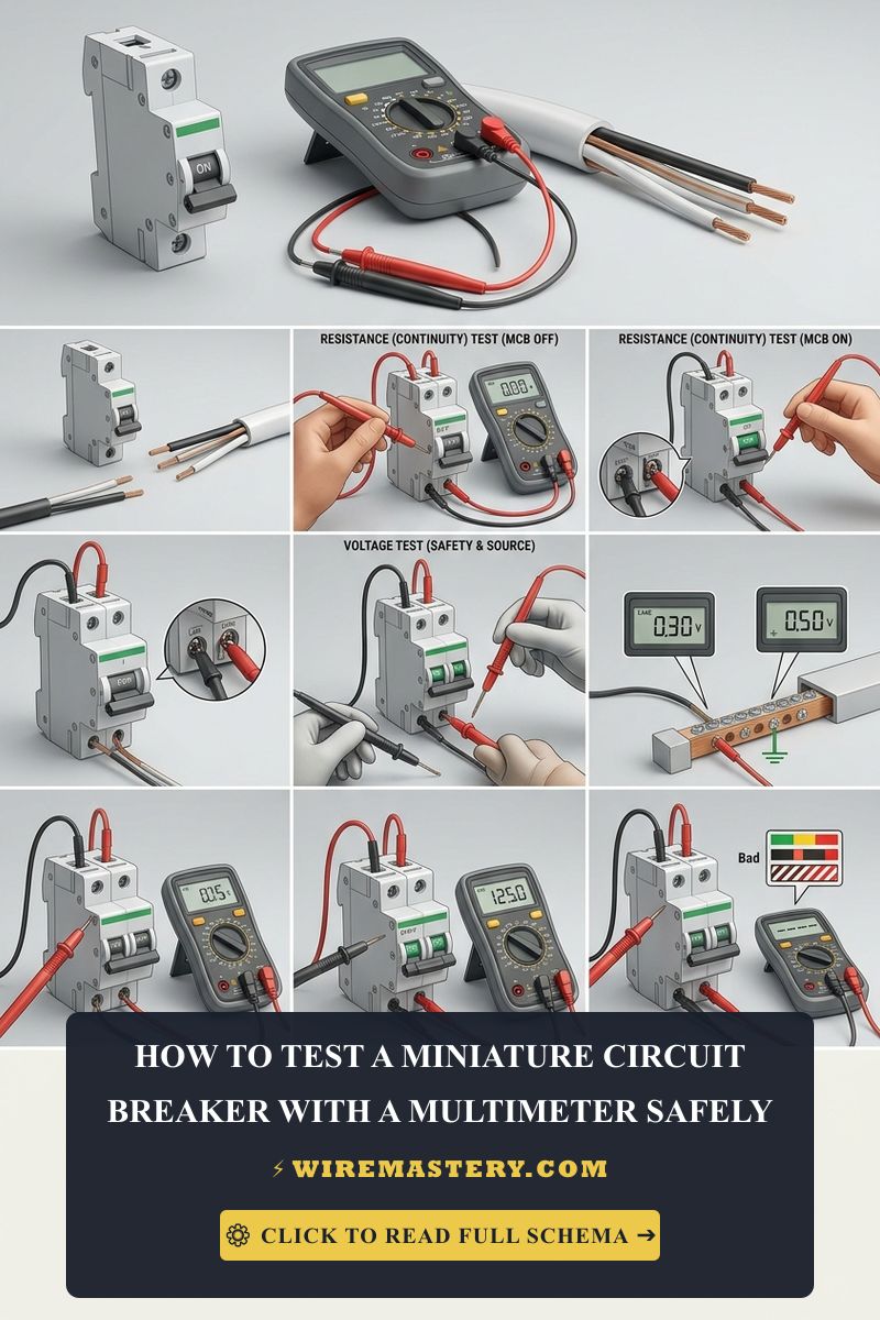
- Toggle the detached circuit breaker handle to the full “OFF” position. Place your black probe onto the rear metal bus bar jaw clip and your red probe onto the terminal wire lug screw screw.
- The System Parameters: The digital screen must read an infinite open loop (O.L.), confirming the internal contact pads are completely separated.
- Toggle the circuit breaker handle to the full “ON” position. Keep the probes anchored on the exact same points.
- Analyze the Ohmmeter Data Display: A properly functioning breaker must emit a continuous loud beep and register a resistance reading below 0.1 Ω. If the meter stays completely silent or registers a floating resistance value exceeding 1.0 Ω, the internal contact faces have accumulated a heavy layer of non-conductive carbon soot from historical short-circuit trips. The breaker is defective and will overheat under load, demanding immediate structural replacement.
Technical Phase 2: Live Voltage Outlets and Millivolt Contact Drop Audits
If your unpowered baseline continuity tests read clear but the target breaker continues to experience premature thermal tripping cycles under normal operational currents, you must execute a live, synchronized voltage and drop audit inside the energized panel board enclosure.
1. The Corrected Outbound Live Voltage Measurement Matrix
To audit whether a circuit breaker is actively delivering full, clean line-voltage potential downstream to its assigned branch circuit network, never probe across the input and output terminals in parallel while the device is switched on. Instead, apply this precise trade safety protocol:
- Put on your Class 00 dielectric rubber work gloves and your high-impact ANSI-rated polycarbonate safety goggles. Ensure your footwear is fully dry and insulated from the concrete floor plane.
- Set your True RMS digital multimeter dial to the AC Voltage setting (V AC). Ensure your black probe is securely inserted into the COM port and your red probe sits inside the VΩ port.
- Anchor your black testing probe firmly onto the main panel Grounded Neutral Bus Bar or the solid copper grounding rail block.
- Touch your red testing probe directly to the terminal wire lug screw (the output load terminal) of the target breaker.
- Analyzing the Meter Parameters: A healthy, code-compliant breaker operating in the full “ON” position must display a nominal line potential between 114V AC and 126V AC (matching the baseline voltage of your master disconnect feed). If the meter registers 0V AC while the switch handle points to “ON,” the internal mechanical linkage has snapped or the contact pads are fully oxidized, rendering the hardware defective.
2. The In-Circuit Contact Millivolt Drop Test Under Peak Load
To identify micro-scale contact degradation that causes a breaker casing line to accumulate extreme heat, measure its internal voltage drop (V_drop) in millivolts while the branch circuit is running under full load:
- Plug a heavy-duty resistive appliance (such as a 1,500-Watt space heater) into an outlet along the branch circuit to draw approximately 12.5 Amps of continuous current.
- Rotate your digital multitester dial to the high-resolution AC Millivolt setting (mV).
- Place your black probe onto the exposed metal bus bar clip at the rear of the target breaker (you can access this via the small diagnostic gap on the breaker side or the panel terminal tabs). Place your red probe onto the terminal wire lug screw of the exact same breaker.
- Analyze the Digital Millivolt Display Readings:
- If the meter reads below 50 mV: The internal contact pads maintain a high-density, low-impedance connection, passing current flawlessly.
- If the meter reads between 50 mV and 100 mV: The breaker is experiencing structural settling. Monitor the line for progressive degradation.
- If the meter exceeds 100 mV: The internal contact resistance has scaled catastrophically. The bimetallic strip is absorbing heat from the micro-volt arc drop, forcing a premature thermal trip. Replace the breaker module immediately to prevent localized subpanel fire risks.
🛠️ Infrared subpanel Maintenance Note: Look closely at the split-phase subpanel layouts and terminal assets showcased across our master electrical installation portfolios. Notice that a failing circuit breaker generating high contact resistance will emit an intense infrared thermal energy footprint before it can trip the branch. Before touching live copper lugs, always execute a non-contact infrared thermal laser sweep over the entire breaker panel casing array. An individual breaker housing registering a temperature reading above 140°F (60°C) while adjacent units float at 95°F (35°C) confirms active contact degradation.
Troubleshooting Common Circuit Breaker Test Faults
- The Multimeter Registers 0V AC on the Load Screw but the Lights are On: This behavior indicates a severe Multi-Wire Branch Circuit (MWBC) or Back-Feed Hazard. An un-certified installer has accidentally cross-connected two independent branch hot lines inside a hidden junction box down the track. Current is looping backward from an adjacent circuit breaker to power the lines. Turn off both breakers immediately to isolate the circuit safely before handling the wiring harnesses.
- The Internal Resistance Reads Clear but the Switch Handle Feels Loose: Indicates a fatigued mechanical trip spring armature. Over decades of seasonal thermal cycles, the internal tension clips lose their elasticity coefficient, preventing the contact pads from pressing together under sufficient mechanical torque. Even if the ohmmeter reads 0 Ohms on the bench, the loose contact pads will chatter and arc under continuous inductive load current spikes, destroying the unit.
- The Breaker Tripps and Refuses to Reset Even When Extracted from the Panel: This symptom confirms a fused solid-state welding fault. If the branch circuit suffered an intense, high-amperage dead short circuit that exceeded the breaker’s nominal Ampere Interrupting Capacity (e.g., a fault blast exceeding 10,000 AIC), the extreme plasma heat will literally weld the silver contact pads together into a single solid slug of metal. The breaker can no longer pivot open to protect the circuit, requiring immediate disposal.
National Electrical Code Breaker & Panel Regulations
Adhering to strict national structural regulations protects your home infrastructure from fire hazards and ensures full property insurance compliance. The National Electrical Code strictly regulates overcurrent protections, component testing clearances, and device grounding integrity under Sub-sections of NEC Article 240 (Overcurrent Protection):
- Regular Operator Testing Directives (NEC Article 240): The NEC mandates that all overcurrent protection devices must be maintained in a pristine, fully operational state, recommending periodic manual exercising and technical resistance testing to guarantee instantaneous trip safety performance during an active infrastructure crisis.
- Manufacturer Compliance Standards (NEC 110.3(B)): Circuit breakers and electrical distribution centers must be tested, evaluated, and deployed strictly in full compliance with the explicit technical instructions and torque boundaries stamped onto the product casing by the original manufacturer.
For the NFPA 70 provisions relevant to this guide on How to Test a Circuit Breaker with a Multimeter Safely, consult the Official NFPA 70: National Electrical Code (NEC).
Conclusion
This guide covers executing unpowered closed-contact resistance checks, computing live millivolt drop calculation matrices, and isolating defective contact faces using CAT III certified auto-ranging multimeters transforms hazardous subpanel troubleshooting into a highly controlled science. By keeping breaker contact resistances below the 0.1-Ohm code-compliant limit, wrapping terminal side screws with premium electrical tape to eliminate enclosure ground shorts, and respecting mandatory NEC Article 240 clearance boundaries, you build an exceptionally resilient residential technology framework. For final checks, complete main switch power isolation safety checks before testing live terminals, deploy insulated square-drive screwdrivers, and complete every diagnostic phase with precision.







