Tankless Water Heater Installation: Electrical & Code Guide
Executing a code-compliant residential tankless water heater installation or infrastructure replacement demands a deep alignment with thermodynamics, structural hydraulic positioning, and heavy-duty dedicated load calculations. Often classified as on-demand hot water distribution matrices, these compact units eliminate stand-by thermal decay by utilizing high-wattage heating element banks or high-input gas burners to heat water instantaneously as it transits the internal copper manifold blocks. However, integrating an electric model requires extreme precision; because these appliances draw massive instantaneous current spikes, an installer must thoroughly audit the property’s primary service load capacity. For home infrastructure managing dual automation and heavy electrical services, ensuring your main panels tie into verified residential service entrance and wire size baselines prevents panel-board bus bar overload failures.
The thermodynamic calculation metrics for flow demand, precise multi-breaker electrical configurations, and National Electrical Code (NEC) load boundaries.
Core Engineering Sizing Parameters
Before unmounting legacy storage tanks or routing high-amperage lines, establish your mechanical sizing metrics:
-
The Flow Rate Demand Index (GPM): Sizing a tankless system is calculated using collective Galons Per Minute (GPM). A standard bathroom faucet demands 0.5 to 1.5 GPM, whereas a high-efficiency shower fixture consumes 2.0 to 2.5 GPM.
-
The Delta T (ΔT) Equation: The required heating capacity relies entirely on the incoming cold groundwater temperature boundary. The system sizing equation is defined as:
ΔT = Target Temperature (typically 120°F) - Incoming Ground Water Temperature
In cold northern climates of the United States where groundwater rests at 40°F, the unit must achieve a high Δ T of 80°F, demanding triple the heating wattage required in southern states.
- The Continuous Load Classification: Tankless water heaters run for sustained periods during multi-point fixture activation states, classifying them as continuous loads under structural definitions.
Technical Materials & Heavy Appliance Commissioning Toolkit
Safely routing high-amperage lines and plumbing multi-point bypass valve grids requires specific heavy-duty trade tooling and testing instruments:
| HVAC / Electrical Trade Tool | Primary Engineering Purpose & Application Spectrum |
|---|---|
| Digital Clamp Multimeter | Category CAT III 600V certified to safely audit live current draws exceeding 100 Amps. |
| Heavy-Duty Hydraulic Lug Crimper | Achieves low-resistance gas-tight crimp connections on thick subpanel grounding lines. |
| Calibrated Torque Wrench | Absolute code requirement to tighten heavy-duty circuit breaker terminal lugs to inch-pound specs. |
| Dual-Phase Non-Contact Tester | Audibly monitors the main panel panel box bus bars to verify complete isolation before work. |
| Heavy-Duty Conduit Wire Puller | Guides thick THHN conductor lines smoothly through rigid PVC or EMT wall conduit tracks. |
The Electric Multi-Breaker Engineering Matrix (NEC Table 310.16)
The single most critical error made by automatic layout tools is under-sizing the wire gauge thickness relative to the overcurrent circuit breaker rating. Electric tankless water heaters do not run on a single wire loop; they combine multiple heating elements that demand up to four independent dual-pole circuit breakers working simultaneously. Bypassing correct wire-to-breaker ratios violates federal code and creates immediate house fire hazards:
Official Electric Tankless Load Sizing Reference Chart
| Total Unit Power (kW) | Total Amperage Draw | Required Circuit Breaker Configuration | Minimum Conductor Gauge (AWG Copper) |
|---|---|---|---|
| 13 kW | 54 Amps | Two (2) x Double-Pole 30-Amp Breakers | Two separate runs of #10 AWG Solid Copper |
| 18 kW | 75 Amps | Two (2) x Double-Pole 40-Amp Breakers | Two separate runs of #8 AWG Stranded Copper |
| 27 kW | 112.5 Amps | Three (3) x Double-Pole 40-Amp Breakers | Three separate runs of #8 AWG Stranded Copper |
| 36 kW | 150 Amps | Four (4) x Double-Pole 40-Amp Breakers | Four separate runs of #8 AWG Stranded Copper |
🚨 Contractor Infrastructure Check: The 200A Service Boundary A standard 27 kW unit draws 112.5 Amps continuous. If your residential property has an older 100-Amp or 125-Amp main panel service, installing an electric tankless unit is physically impossible without executing a full utility service upgrade to a 200-Amp or 400-Amp master distribution panel.
Step-by-Step Field Installation and Multi-Conductor Termination Blueprint
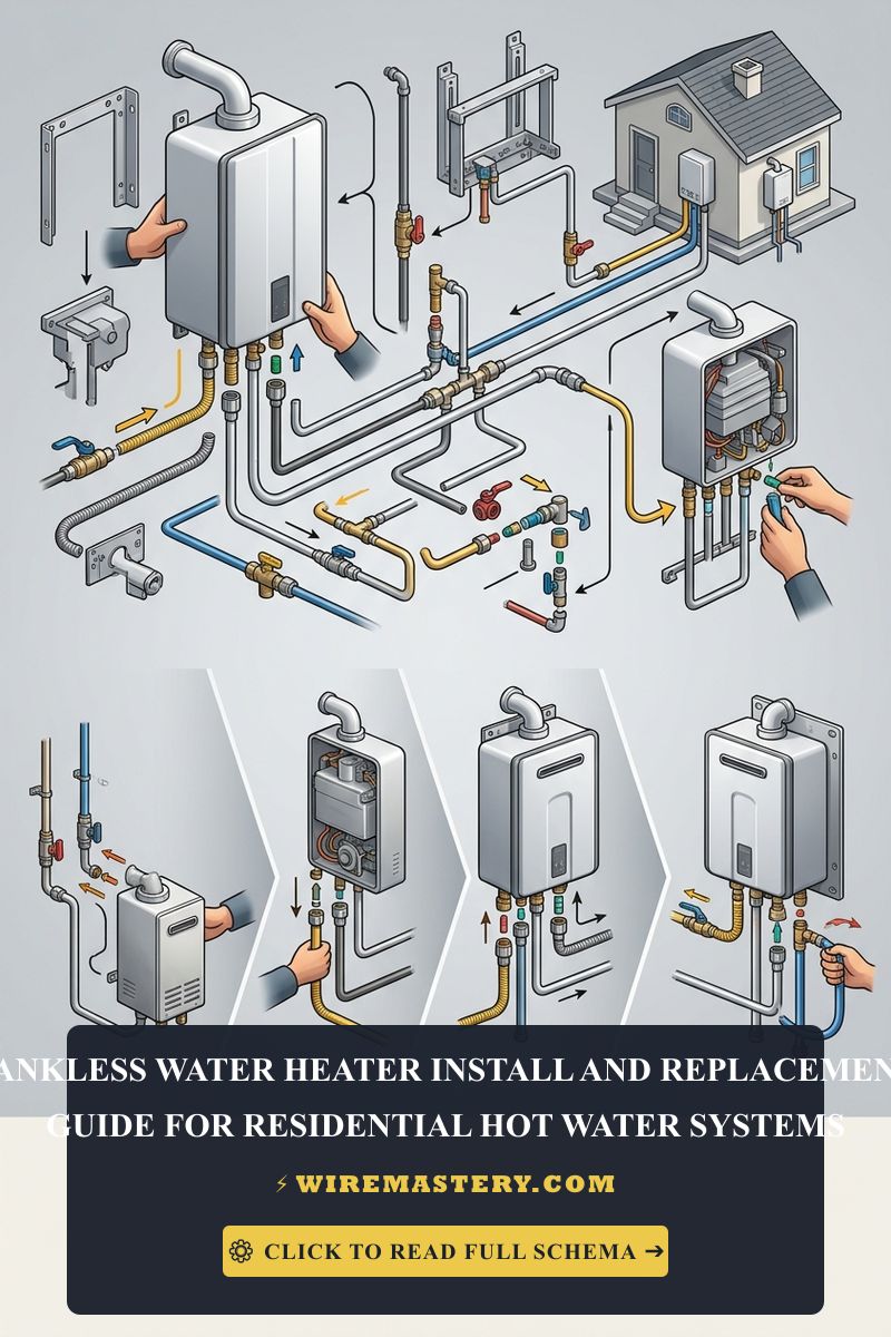
Executing a tankless water heater upgrade requires managing high-density plumbing manifolds alongside complex multi-breaker service taps. Follow this systematic trade sequence to complete the deployment safely:
1. Hard Infrastructure Utilities Isolation
Locate your property’s primary distribution panel center. Toggle the main service disconnect switch completely off, or isolate all individual multi-pole circuit breakers feeding the utility zone. Shut off the main municipal water valve entering the structure and completely isolate the gas service stop-cock if retrofitting a gas-fired model. Verify all terminal leads read a true 0V AC state using your dual-phase tester before handling any components.
2. Physical Structural Mounting and Plumbing Integration
Secure a solid 3/4-inch backing plywood panel directly onto the wall studs to support the weight of the heating chassis. Mount the tankless unit square and level using your framing screws.
- Connect the incoming cold water supply line to the Blue inlet port and route the hot water line out from the Red outlet port.
- Mandatory Service Valve Installation: You must install a specialized set of isolation flush valves (Webstone valves) directly onto both ports. These valves feature side-access ports that enable technicians to pump chemical solvents into the heating core during routine maintenance without cutting the property’s main water connections.
3. Terminating the Multi-Circuit Electrical Feed (Electric Units Only)
Route your multiple independent #8 AWG or #10 AWG Romex cable lines directly from your subpanel into the unit’s integrated wiring terminal gutter enclosure.
- Strip exactly 1/2 inch of insulation off the stranded copper cores using your heavy-duty cutters.
- Insert the conductor ends into the assigned terminal lug slots. Circuit 1 must attach to Terminal Block A, Circuit 2 to Terminal Block B, and so on. Never tie or parallel multiple wire lines onto a single terminal block port.
- Use your calibrated torque wrench to tighten the lugs to the manufacturer’s exact inch-pound specification to prevent localized micro-arcing. Bond all bare equipment safety grounding wires firmly to the central chassis grounding lug block.
🛠️ Gas Venting Safety Note: Look closely at the ventilation layouts displayed across our modern gas-fired mechanical schematics. Notice that high-efficiency gas tankless units output highly acidic condensation runoff during operation. Under building codes, you are strictly required to use Category III or Category IV stainless steel or certified solid PVC venting pipes to exhaust carbon monoxide flue gases horizontally out through the exterior wall envelope. Utilizing old, non-sealed B-vent aluminum chimney pipes will cause the corrosive condensation to rot the vent walls, leaking lethal carbon monoxide gases back into the residential living spaces.
Maintenance Phase: Annual Descaling & Core Flushing Blueprint
Unlike traditional storage tanks that slowly accumulate sediment at the floor base, a tankless unit’s internal copper heat exchanger copper tubes suffer from rapid mineral scaling. As hard water passes through hot elements, calcium carbonate bakes onto the tube wall linings, choking water channels and dropping heating efficiency. Follow this contractor descaling routine at least once a year:
- Isolate the electrical circuit breakers completely to ensure zero power feeds the elements. Close both the main cold and hot water service isolation valves.
- Connect a pair of standard washing machine rubber hoses to the side flush ports of your Webstone isolation valves. Place the opposing ends of the hoses into a 5-gallon utility bucket.
- Submerge a small submersible utility pump inside the bucket. Attach the cold-side hose to the pump output nozzle. Fill the bucket with 3 gallons of food-grade pure biodegradable descaling solution or pure white vinegar.
- Open both side flush valve ports. Turn on the submersible pump. Let the pump circulate the acid solvent through the tankless heat exchanger core loops continuously for 45 to 60 minutes. The acid will chemically dissolve the internal calcium build-up, flushing scale chunks out into the bucket.
- Turn off the pump, discard the dirty fluid, flush the internal lines with clean municipal tap water for 5 minutes, close the flush ports, re-open your main house valves, and re-engage the circuit breakers.
Troubleshooting Common Tankless System Failures
- The Unit Shuts Down Suddenly with a “Minimum Flow” Error Code: Tankless units utilize an internal flow sensor paddle wheel to confirm water is moving before energizing elements. If a homeowner opens a faucet very slowly, or if the inlet cold water mesh filter is choked with water-main rust sediment, the unit drops below its activation threshold (typically 0.5 GPM), cutting power instantly. Pull the cold-side inlet filter screen and purge the sediment debris under clean running water.
- The Water Temperature Fluctuates Drastically (The Cold Water Sandwich): This occurs when a user turns a faucet on, turns it off, and instantly turns it back on. A pocket of unheated cold water enters the line between cycles. If the issue is chronic, it indicates a failing internal modulation gas valve or scaling on the temperature sensor thermistor. Clean the thermistor casing with fine steel wool.
- The Main Circuit Breaker Trips Immediately on Long Showers: An absolute indicator of an overcurrent code violation. This happens when an un-certified installer hooks a 27 kW unit up to a set of breakers without verifying the total service panel headroom. As additional house appliances (like a clothes dryer) engage while the heater pulls its full 112 Amps, the master panel main lug overheats, tripping the primary 200A house disconnect. Conduct a formal home load calculation and upscale your master panels capacity.
National Electrical Code Appliance Sizing Regulations
Adhering to strict construction regulations protects your property value, ensures full insurance compliance, and shields your family against high-amperage electrical hazards. The National Electrical Code strictly regulates heavy-duty water heaters, continuous space heating equipment, and branch calculations under NEC Article 220 (Branch-Circuit, Feeder, and Service Load Calculations) and Article 422 (Appliances):
- Appliance Load Sizing Rules (NEC 422.13): A fixed electric storage or instantaneous water heater must be treated as a continuous load. The branch circuit overcurrent protection device (breaker) and conductor size must be calculated at 125% of the appliance’s total nominal rated current load, ensuring full thermal headroom inside panel gutters.
- Feeder Demand Factors (NEC Article 220): When performing load calculations to verify if a residential home service panel can safely handle a tankless heater addition, no demand factor reduction is allowed for on-demand electric water heating elements; they must be added to the calculation matrix at a full 100% of their maximum kilowatt rating.
For the NFPA 70 provisions relevant to this guide on Tankless Water Heater Installation: Electrical & Code Guide, consult the Official NFPA 70: National Electrical Code (NEC).
Conclusion
This guide covers executing residential tankless water heater installation load calculations and mastering multi-breaker wiring layouts transforms complex appliance retrofits into safe, electrical frameworks. By applying strict wire-to-breaker ampacity matching benchmarks, executing annual acid descaling flushes to eliminate mineral scaling insulation barriers, and enforcing absolute compliance with NEC Article 422 continuous load calculations, you build a resilient and highly optimized home grid infrastructure. For final checks, complete electrical panel power de-energization checks, utilize CAT III certified digital clamp meters, and complete every terminal step with safety-first precision.