How to Wire a Split Air Conditioner: HVAC Electrical Guide
Introduction
Engineering a reliable, code-compliant residential mini-split air conditioning circuit deployment demands an advanced structural understanding of dual-phase line-voltage parameters, inductive current dynamics, and specialized outdoor environment sealing metrics. Unlike standard 120V household appliances that operate via a single hot track and a grounded neutral return line, modern high-efficiency split-system heat pumps and inverter compressors utilize a 208V/240V AC dual-phase electrical supply framework. This grid demands two individual, synchronized hot supply conductors operating without a traditional neutral wire loop. For setups driving advanced whole-house automation and climate arrays, ensuring your incoming mechanical feeder panels maintain strict alignment with verified residential electrical panel loading and wire size charts avoids transient harmonic voltage dropouts.
The 240V wiring matrices for outdoor condenser nodes, the mechanical routing of shielded four-conductor interconnect control links, and National Electrical Code (NEC) continuous loading boundaries.
Core HVAC Circuit Sizing Metrics
Before routing high-voltage conductor pathways through finished walls or pulling solid copper cores into conduit lines, decode these foundational engineering thresholds:
- The 240V Line-to-Line Matrix: A dedicated mini-split outdoor condenser terminal block does not feature a neutral slot. Potential difference is established exclusively between two hot phases (L1 and L2), each delivering 120V relative to the system ground bar, totaling 240V AC line-to-line potential.
- MCA vs. MOP Parameters: Technicians must strictly evaluate the manufacturer data plate stamped onto the side of the condenser shroud casing. You must size your circuit conductors based on the Minimum Circuit Ampacity (MCA) rating, and select your dedicated overcurrent protection device based on the Maximum Overcurrent Protection (MOP) rating.
- The Liquidtight Flexible Nonmetallic Conduit (LFNC) Mandate: All exterior high-voltage feeder wire lines running from the safety disconnect box to the condenser entry port must be enclosed within an unbroken liquid-tight conduit jacket to isolate current tracks from moisture, uv exposure, and lawn maintenance hazards.
Technical Materials & High-Amperage HVAC Commissioning Toolkit
Safely opening electrical disconnect boxes and executing low-resistance gas-tight terminal compressions requires specific heavy-duty tools and certified testing instrumentation:
| HVAC Electrical Tool | Primary Engineering Purpose & Safety Threshold |
|---|---|
| True RMS Digital Clamp Meter | Category CAT III 600V certified to safely capture continuous startup current spikes. |
| Eccentric Flaring Tool Kit | Formulates uniform, mirror-smooth 45° flare connections on structural copper refrigerant tubes. |
| Ratcheting Terminal Crimper | Compresses insulated fork or spade lugs onto fine-stranded switch bypass wiring harnesses. |
| Dual-Phase Non-Contact Tester | High-sensitivity tester calibrated to detect ambient electromagnetic fields before bare skin contact. |
| Calibrated Dial Torque Wrench | Absolute requirement to torque down line terminals and flare nuts to exact inch-pound specifications. |
Sizing HVAC Conductor Profiles & Circuit Breaker Capacities
The absolute leading cause of catastrophic structural residential fires during DIY air conditioning upgrades is under-sizing the wire gauge thickness relative to the overcurrent circuit breaker rating. Mini-split installations are continuous high-inductivity loads regulated strictly by NEC Article 440 guidelines:
- 12 AWG Solid Copper Conductor (20-Amp Breaker Limit): Paired inside a yellow Romex jacket for interior runs or routed as independent THHN strands inside outdoor conduits. Required for small 9,000 to 12,000 BTU systems exhibiting low MCA thresholds.
- 10 AWG Solid or Stranded Copper (30-Amp Breaker Limit): Paired inside an orange jacket. Mandatory for large 18,000 to 36,000 BTU multi-zone mini-split outdoor condensers to withstand intensive continuous compressor loading cycles without thermal wire breakdown.
- The Communication Cable Requirement (14/4 Stranded THHN Shielded): The path interconnecting the indoor evaporator unit to the outdoor condenser utilizes a specialized heavy-duty tray cable (Mini-Split Cable). It incorporates three current-carrying stranded conductors (Lines 1, 2, 3) alongside an uninsulated green safety grounding core, enclosed within an integrated foil shield to prevent electromagnetic interference from corrupting digital data logs.
Step-by-Step Field Blueprint: Wiring the Outdoor Disconnect & Split System
Executing the electrical deployment of a split air conditioning network requires split-phase main panel taps and weatherproof enclosure terminations. Follow this systematic trade sequence to complete the installation safely:
1. Hard Panel Circuit Isolation Protocol
Locate your property’s primary service distribution panel. Identify and disengage the dedicated dual-pole circuit breaker assigned to the HVAC loop, locking the switch handle using a universal LOTO padlock clamp. Before backing out any factory deadfront screws on the outdoor disconnect box, verify a true 0V AC state across all lines using your dual-phase tester.
2. Wiring the Weatherproof Outdoor Disconnect Box (NEC 440.14)
- Mount a certified, rain-proof NEMA 3R non-fused or fused disconnect enclosure box square onto the exterior wall framing, maintaining a minimal 3-foot clearance envelope from structural utility gas meters.
- Route the incoming 240V lines from the indoor subpanel into the disconnect box housing via rigid PVC conduit tracks. Connect the two hot conductors (typically Black and Red) directly onto the terminal lugs stamped LINE 1 and LINE 2.
- Route fresh THHN stranded copper conductors out from the disconnect switch assembly through a flexible liquid-tight nonmetallic conduit (LFNC) loop heading to the condenser. Secure these lines onto the pressure plates stamped LOAD 1 and LOAD 2. Bond all bare and green ground conductors firmly to the integrated subpanel grounding terminal block strip.
3. Terminating the 14/4 Interconnect Communication Link
- Feed your shielded 14/4 stranded mini-split cable through the sloped 3-inch wall penetration hole alongside the copper refrigerant lines and condensate drain track.
- At the Indoor Evaporator Unit: Strip exactly 1/2 inch of insulation off the fine wire strands, crimp insulated fork terminal lugs onto each core, and anchor them directly to the terminal strip blocks matching factory codes: Terminal 1 (L1 Power), Terminal 2 (L2 Power), and Terminal 3 (Digital Signaling Data). Tie the green wire to the chassis frame grounding screw block.
- At the Outdoor Condenser Unit: Route the other end of the 14/4 cable into the low-voltage isolation compartment slot. Wire the cores to the exact matching terminals: 1 to 1, 2 to 2, and 3 to 3. 🚨 Critical Warning: Crossing Terminal 2 and Terminal 3 during field installation will apply a raw 120V potential directly onto the sensitive communication logic microprocessor rail, destroying the main inverter control boards instantly.
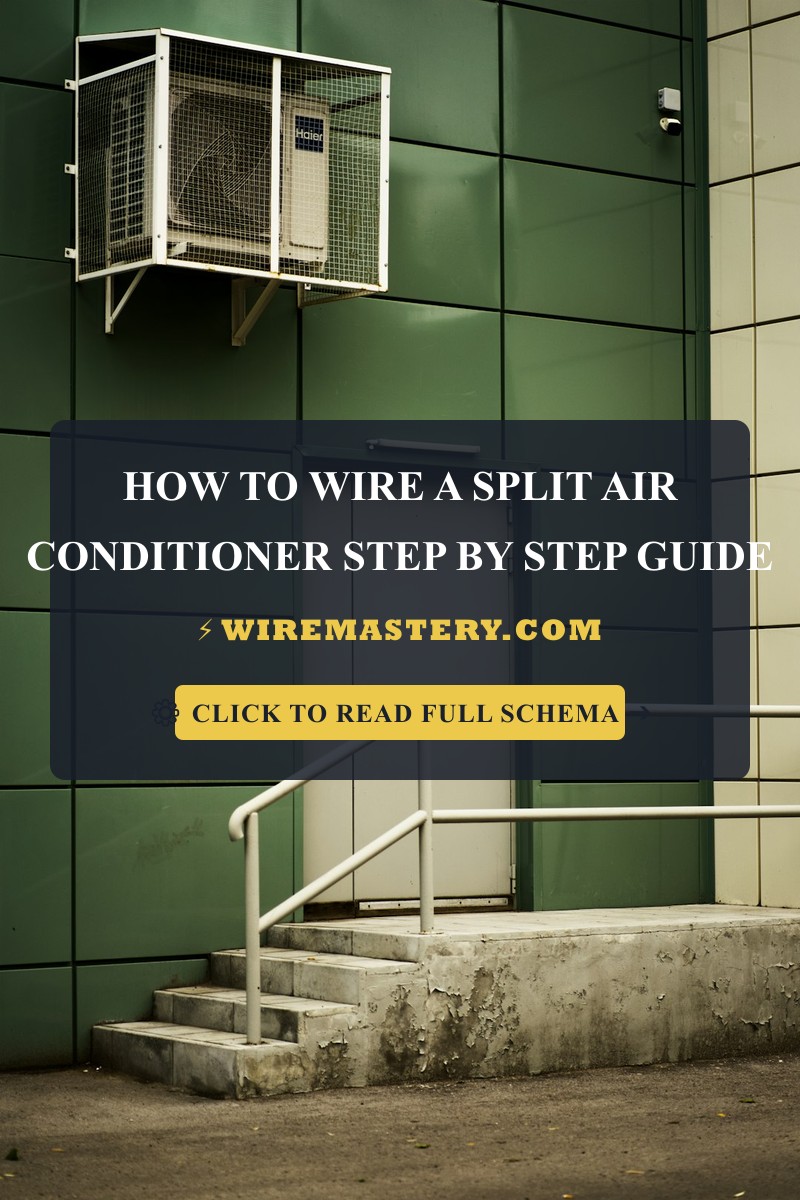
🛠️ Condenser Isolation Placement Note: Look closely at the structural equipment layouts displayed across our technical HVAC portfolios. Notice that high-amperage rotary compressors generate continuous dynamic micro-vibrations during active cooling cycles. Always anchor the outdoor condenser base feet firmly onto a heavy-duty composite or concrete mounting pad using integrated anti-vibration rubber isolation pucks. Bypassing these rubber dampers allows mechanical vibration frequencies to transfer into the building wall studs, causing loud humming noises throughout the home interior.
Troubleshooting Common Split System Electrical Failures
- The Indoor Unit Powers On but the Outdoor Compressor Stays Dead: This behavior indicates a faulty outdoor loop contactor relay or a tripped high-pressure safety switch. Open the electrical gutter panel of the condenser and use your multimeter to check voltage across the side coil terminals of the contactor block. If the meter registers a healthy 240V AC but the mechanical plunger fails to pull inward, the internal solenoid coils are burned out. Replace the contactor assembly immediately.
- The Main Dual-Pole Circuit Breaker Trips the Millisecond the AC Starts: An absolute indicator of a dead short circuit or a grounded compressor winding. This happens when internal motor insulation degrades over extensive duty cycles, allowing raw line voltage to touch the steel hermetic casing. Turn off the disconnect switch and use your multimeter in unpowered resistance mode to check the pins (C, R, S) relative to the copper pipe ground. If the meter beeps, the compressor is dead, demanding a full hardware overhaul.
- The System Throws a Constant “Communication Link Open” Error Code: This indicates an unshielded data line or high-frequency inductive noise contamination. If an installer routed a standard unshielded thermostat wire instead of a 14/4 shielded tray cable, inductive interference from adjacent 240V compressor supply lines will scramble the digital data packet frames. Swap out the run for a certified, shielded 14/4 mini-split cable harness and bond the foil shielding layer exclusively to the equipment rack ground bar.
National Electrical Code HVAC Safety Regulations
Adhering to strict national installation codes protects your property value, ensures full insurance compliance, and shields your family against high-voltage electrical fire hazards. The National Electrical Code strictly regulates continuous air conditioning loads, disconnect clearances, and conductor feeds under NEC Article 440 (Air-Conditioning and Refrigerating Equipment):
- Disconnecting Means Line-of-Sight Compliance (NEC 440.14): A dedicated physical disconnecting switch assembly must be installed within clear, un-obstructed sight of the air conditioning equipment and be easily accessible. The maximum structural distance from the disconnect box to the condenser frame must not exceed 50 feet, ensuring a field technician can instantly slice power during an emergency arc-flash event.
- Overcurrent Protective Headroom (NEC 440.22): The branch circuit overcurrent protection device must be capable of carrying the massive inrush locked-rotor current spikes without tripping, allowing sizing limits to scale up to 175% or 225% of the compressor’s rated load current if standard thermal breakers experience nuisance tripping.
For the NFPA 70 provisions relevant to this guide on How to Wire a Split Air Conditioner: HVAC Electrical Guide, consult the Official NFPA 70: National Electrical Code (NEC).
Conclusion
This article explains split system MCA/MOP parameters, installing weatherproof NEMA 3R safety disconnect boxes with correct line-of-sight clearances, and terminating shielded 14/4 stranded communication links to strict matching terminal matrices transforms chaotic mini-split upgrades into safe, predictable electrical operations. By keeping conductor sizes completely aligned with NEC Article 440 overcurrent boundaries, avoiding backstabbed terminal play, and enforcing absolute grounding continuity across indoor and outdoor chassis frames, you construct an unshakeable, resilient home grid environment. For final checks, complete panel breaker power isolation safety checkups before handling lines, deploy CAT III certified True RMS clamp meters, and execute every maintenance phase with precision.