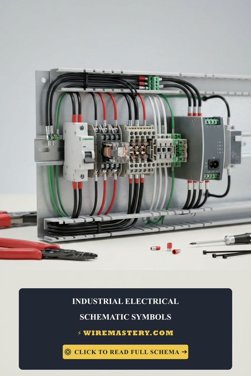
Industrial Electrical Schematic Symbols: Complete NEMA & IEC Guide
Reading industrial electrical drawings requires familiarity with standardized symbols, device tags, ladder logic, and the separation between power and control circuits. This guide explains the common industrial electrical schematic symbols used for control panels, programmable logic controller (PLC) cabinets, motor control centers (MCC), relays, and three-phase motor starters.
For safe design and commissioning, drawings should identify the applicable standard, voltage level, conductor functions, terminal numbers, and protective devices. For related conductor-sizing background, see our 100A subpanel wire size and breaker selection guide.
The guide focuses on schematic conventions, contact states, component designations, and the information needed to interpret industrial electrical drawings accurately. Always verify symbols against the project standard, manufacturer documentation, and the drawing legend.
Global Standardization Frameworks: NEMA vs. IEC
Industrial drawings commonly use NEMA/ANSI or IEC conventions, but the exact symbol library and layout depend on the project standard and drawing legend:
- NEMA / ANSI conventions: Common in North American industrial documentation and often used with ladder-logic layouts, device tags, and control-circuit conventions defined by the project.
- IEC conventions: Common in international documentation and often associated with modular symbol libraries, reference designations, and compact control-system layouts. Neither convention should be inferred solely from geography; use the drawing legend and applicable standard.
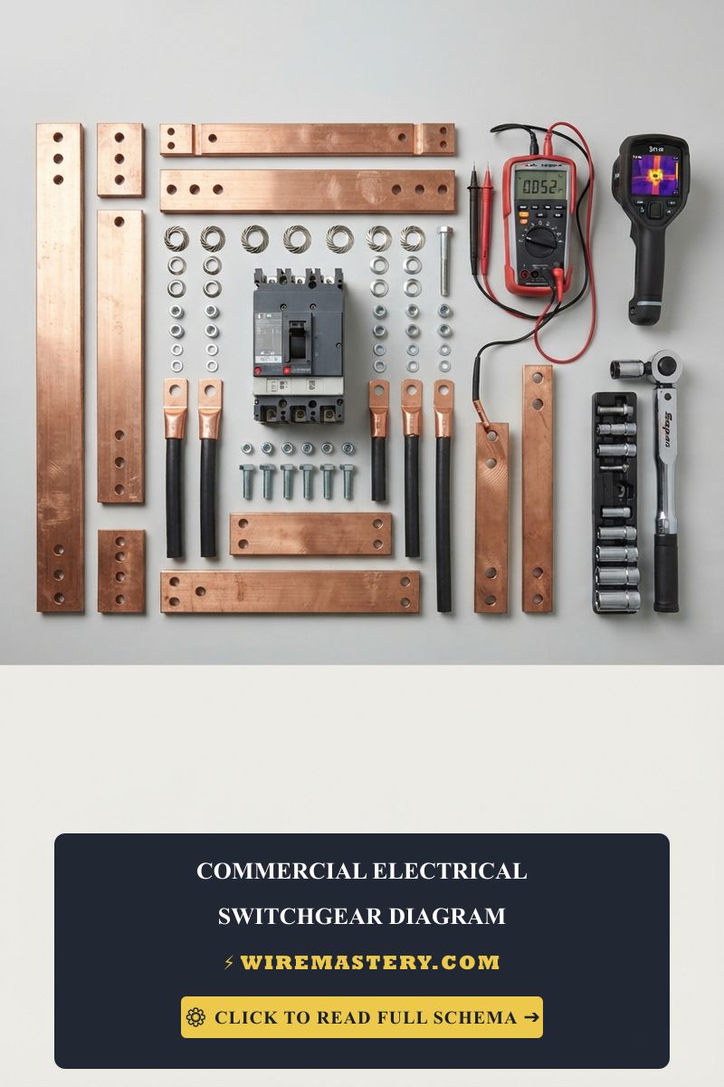
Technical Materials & Blueprint Auditing Toolkit
Successfully translating flat schematic symbols into safe physical wiring arrays inside an active subpanel enclosure requires specific diagnostic instruments and validated hand tools:
| Engineering Drafting Tool | Primary Technical Purpose & Blueprint Application |
|---|---|
| Industrial CAD Software Suite | Used to generate multi-layer schematic tracks and execute automated wire-numbering scripts. |
| True RMS CAT IV Multimeter | Validates the physical terminal locations matching the schematic pin numbers during diagnostic runs. |
| Calibrated Loop Calibrator (4-20mA) | Simulates active control signals across analog instrumentation loops mapped on drawings. |
| Insulated Wire Marker Labels | High-density numbers wrapped around conductors matching the exact line numbers of the print. |
| Laser Distance Measuring Wand | Computes true raceway path lengths to prevent uncalculated line attenuation behind panels. |
Primary Power & Control Circuit Symbol Matrices
To interpret an industrial single line diagram or a multi-sheet ladder schematic flawlessly, engineers categorize symbols into functional circuit blocks. The foundational layer centers on primary power components and overcurrent protection devices:
1. Multi-Phase Overcurrent Disconnect Mechanisms
Industrial power distribution systems may use three-phase lines (A, B, and C phases). The schematic should identify the linked poles, voltage level, protective device, and control function:
- Molded Case Circuit Breaker (MCCB): The exact graphic varies by symbol library. Confirm the interrupting rating, trip function, pole linkage, and reference designation from the drawing legend and device documentation.
- Thermal Overload Relay: The symbol and reference designation vary by standard. Its function is to monitor motor overload and operate an associated control contact; it is not a substitute for short-circuit protection.
Technical Text Blueprint: Three-Phase Motor Control Layout
To visualize how primary power symbols interface with secondary low-voltage control loop circuits, technical designers reference standard ladder-logic schematics. Notice how the high-voltage power paths are separated from the logic tracks:
  [ High-Voltage 480V Line ] ───[█ Main Disconnect Breaker ]
                                      │
         ┌────────────────────────────┼────────────────────────────┐
         ▼ (Phase A)                  ▼ (Phase B)                  ▼ (Phase C)
     [───○ Contact M1 ───]        [───○ Contact M1 ───]        [───○ Contact M1 ───]
         │                            │                            │
     [───⚠️ Overload OL ───]     [───⚠️ Overload OL ───]     [───⚠️ Overload OL ───]
         │                            │                            │
         └────────────────────────────┼────────────────────────────┘
                                      ▼
                                 (Ⓜ️ 3-Phase Motor)

  ───────────────────────────────────────────────────────────────────────────────
  [ Low-Voltage 120V Control Logic Track ]

    L1 ───[ Stop PB (NC) ]───[ Start PB (NO) ]───[ (M1) Contactor Coil ]─── L2 / return
                         │               │
                         └────[ M1 (NO) ]┘  <- Auxiliary Sealing Contact Link
Secondary Control Logic: Auxiliary Contacts & Interlocking Sequences
Beneath the primary high-voltage utility feeds sits the brain of the industrial machine: the secondary control logic loop. Technicians interpret these low-voltage lines to audit the automated interlocking sequences that protect heavy machinery from switching on out of order. To track the flow of control current through a ladder diagram, you must master the mechanics of auxiliary contact symbols.
Unlike main power contacts designed to interrupt hundreds of Amperes of arcing current, auxiliary contacts handle small milliampere currents to signal state changes to microprocessors or contactor coils. They are categorized under two immutable mechanical states:
- Normally Open (NO) Contacts: Shown as an open contact in the drawing’s de-energized or normal reference state. The exact graphic depends on the symbol library. The contact closes only when its controlling device or coil operates.
- Normally Closed (NC) Contacts: Shown as a closed contact in the drawing’s de-energized or normal reference state. When the associated relay or device operates, the contact opens; confirm the intended behavior from the sequence description and device documentation.
Industrial Lettering Conventions & Device Designations
An industrial electrical schematic sheet becomes unreadable if components lack structured alphanumeric indexing. To maintain absolute cross-referencing alignment across multi-page drawing packages, the global engineering community enforces standardized device identification lettering codes. Installers map these short codes directly onto physical terminal labels inside the panel enclosures:
| Standard Letter Tag | Primary Hardware Entity | Blueprint Application & Functional Boundary |
|---|---|---|
| CR | Control Relay | Small multi-pole relays used to isolate logic loops or multiply low-voltage signaling tracks. |
| M | Motor Contactor | Heavy-duty electromagnetic switches designed to close primary three-phase utility feeds. |
| OL | Overload Relay | Bimetallic or solid-state thermal monitoring units that protect motors from overcurrent decay. |
| PB | Push Button | Manual user interface triggers, labeled as NC for Stop commands or NO for Start sequences. |
| SOL | Solenoid Valve | Electromagnetic coils that shift hydraulic or pneumatic directional control valve spools on machinery. |
| LS | Limit Switch | Mechanical position tracking sensors deployed to register physical machine component limits. |
| DISC | Disconnect Switch | Main manual rotary handles used to isolate raw incoming line voltage from subpanel backplates. |
Timed Contacts & Advanced Control Logic Symbols
When automated industrial sequences require explicit delays between machine operations—such as staging the startup of three massive exhaust fans to prevent a massive voltage sag at the main distribution panel—designers deploy timing relays. Interpreting these advanced symbols requires analyzing the geometric directional anchors attached to the standard contact lines:
1. Normally Open, Timed-Closed (NOTC) / On-Delay Relays
The NOTC symbol features the standard parallel Normally Open lines, but incorporates a small geometric arrow or parachute hood contour pointing upward away from the contact gap.
- The Operational Trigger: When the timing relay coil receives full control voltage, the contacts do not close immediately. The unit pauses for a pre-configured duration (e.g., 5 seconds) until the internal timing mechanism expires, forcing the parallel bars to snap shut and initialize the downstream sequence. If power is cut to the coil, the contacts drop open instantly with zero delay.
2. Normally Closed, Timed-Open (NCTO) / Off-Delay Relays
The NCTO symbol uses the standard Normally Closed crossed parallel line configuration, paired with a small geometric arrow contour pointing downward into the contact line.
- The Operational Trigger: When voltage hits the off-delay timing relay coil, the contacts break open instantly to cut downstream power. However, the true timing loop initializes the exact second the parent coil is de-energized. Instead of resetting back to a closed state immediately, the timing clock ticks down while the contacts hang open in mid-air, closing only after the pre-set tracking duration finishes.
Troubleshooting Discrepancies in Industrial Blueprints
- An Auxiliary Contact Reads Closed in Field Audits but Logs Open on Print Layouts: This widespread tracking failure confirms a De-Energized State Misinterpretation or a Cross-Wiring Error. Standard engineering practices mandate that all schematic symbols must be drawn in their shelf-resting state, meaning completely unpowered, with zero current flowing and zero mechanical pressure applied to sensors. If a limit switch is physically held down by a heavy machine bracket in its normal resting position on the floor, its real-world electrical state will invert relative to the unpowered print layer, requiring technicians to execute live resistance checks to isolate the line path.
- The Pilot Indicating Light Array Remains Silent Under Active Load: Check the wire tracking numbers against the physical terminal block distribution tracks. If an installer routes a low-voltage LED indicator loop using raw line-to-line 480V metrics instead of referencing the step-down control transformer (CPT) secondary symbols, the light casing will experience an instant overvoltage burst, burning out the solid-state indicator layers within milliseconds.
National Electrical Code Wire Color-Coding Compliance Matrices
Transforming schematic symbols into a physical control cabinet requires the applicable edition of NFPA 79, NEC requirements, IEC 60204-1 where applicable, local rules, and the machine manufacturer’s documentation. Color conventions are not universal across every project, so confirm them from the drawing legend and installation standard:
- Black conductors: Often used for ungrounded power conductors, subject to the project standard.
- Red conductors: Often used for AC control wiring in some North American schemes; verify the legend.
- Blue conductors: Commonly used for DC control wiring in some schemes; verify the legend and voltage class.
- White or gray conductors: May identify grounded conductors where permitted by the applicable code.
- Green, green/yellow, or bare conductors: Commonly reserved for protective grounding; follow the applicable code and machine standard.
For current requirements affecting industrial machinery wiring, grounding, control panels, and electrical safety, consult the Official NFPA 70: National Electrical Code (NEC), the applicable edition of NFPA 79, and the project drawing legend.
Frequently Asked Questions (FAQ)
What NEMA standard defines symbols commonly used in industrial control systems?
The NEMA ICS 19-2002 (Industrial Control and Systems) standard defines the electrical schematic symbols commonly used in North American industrial control systems, providing a consistent design framework alongside the ANSI Y32.2 / IEEE 315 standards.
How do you identify NEMA and IEC pressure switch symbols?
- NEMA Pressure Switch: Features a standard normally open (NO) or normally closed (NC) contact symbol with a mechanical connection linked to a small square or a “P” indicator representing the pressure element.
- IEC Pressure Switch: Uses a rectangular contact block where the actuation method is represented by a specific qualifying symbol for pressure (usually a small piston or diaphragm diagram) according to the IEC 60617 standard.
Conclusion
Use the drawing legend and applicable NEMA/ANSI, IEC, NEC, and NFPA 79 requirements before interpreting an unfamiliar symbol or changing a control-panel connection. Keep high-voltage power paths separate from control circuits, verify the de-energized state before continuity testing, and restrict live measurements on 480V or higher systems to qualified personnel using properly rated equipment.