Residential Electrical Troubleshooting: Sizing Voltage Drops
Executing systematic, residential electrical troubleshooting across a complex branch circuit network demands a deep understanding of circuit loop resistance, Ohm’s law dynamics, and line-voltage attenuation. While sudden overcurrent events instantly trip panel breakers, progressive internal infrastructure decay—such as loose wire nut splices or severely oxidized receptacle terminal screws—typically manifests through severe local voltage drops under heavy appliance loads. When a high-draw device (like a microwave oven or space heater) engages, these high-resistance hotspots choke the current loop, causing nearby lights to dim drastically and starving downstream equipment of voltage. For properties protecting delicate electronics, ensuring your branch lines maintain full compliance with uninterruptible power supply infrastructure guidelines isolates automated hardware from volatile line sags.
The mathematical equations for voltage drop calculations, the physical tracking of localized resistance anomalies, and step-by-step multitester diagnostics under active load conditions.
Core Circuit Sizing Parameters
Before inserting your multitester probes into any energized receptacle slot or handling terminal copper leads, decode these foundational engineering thresholds:
- The 3% Branch Code Limit: Under the strict mandates of NEC Article 210.19(A) Informational Note 4, the maximum allowable voltage drop on a local residential branch circuit must not exceed 3% of the nominal line voltage under full design load conditions. For a standard single-phase 120V AC loop, this limits the maximum allowable drop to exactly 3.6V AC, keeping terminal voltage at or above 116.4V AC.
- The 5% Combined System Limit: The cumulative voltage drop across both the primary service entrance feeder conductors and the final branch circuit loop combined must never exceed 5% overall (a total drop of 6.0V AC on a 120V system), ensuring appliances receive a minimum of 114.0V AC.
- The Conductor Length Factor: Internal copper resistance scales linearly with distance. Running a standard #14 AWG solid copper conductor past 50 feet inside a wall cavity will dramatically amplify voltage drops, requiring an intentional upscale to #12 AWG wire to stabilize the circuit profile.
Technical Materials & Load Fluctuation Auditing Toolkit
Safely tracking localized resistance anomalies and measuring physical conductor voltage drops under continuous loads requires specific testing equipment and insulated hand tools:
| Electrical Troubleshooting Tool | Primary Engineering Purpose & Safety Threshold |
|---|---|
| True RMS Digital Multimeter | Category CAT III 600V certified to capture millivolt drops across energized terminal paths. |
| SureTest Circuit Analyzer | Specialized microprocessor-driven tester that applies a temporary 15A load to calculate true line drops. |
| Non-Contact AC Voltage Detector | Audibly monitors the junction box perimeter to ensure an absolute de-energized work area. |
| Insulated Linesman Screwdrivers | Cushion-grip drivers rated for 1000V AC to torque down terminal screws safely. |
| High-Leverage Cable Cutters | Hardened jaws designed to cut back oxidized or brittle solid copper wire tips cleanly. |
The Mathematics of Line Attenuation: Sizing Voltage Drops
To accurately troubleshoot long wire runs during a home automation retrofit, a field engineer calculates the expected single-phase voltage drop (V_d) using the standard geometric copper resistance equation:
V_d = (2 × K × I × L) / C_cm
Where:
- K (Direct Current Resistance Coefficient): The constant specific resistance of copper at standard operating temperatures (typically 12.9 Ohms per circular mil-foot).
- I (Amperage Load): The active current passing through the line branch under peak load (e.g., a 15-Amp continuous load).
- L (One-Way Distance): The total physical length of the single conductor run measured in feet from the panel bus bar to the furthest outlet.
- C_cm (Conductor Cross-Section Area): The physical circular mil area of the wire gauge profile derived from official standard reference parameters (e.g., 4,110 circular mils for #14 AWG wire or 6,530 circular mils for #12 AWG wire).
🚨 Contractor Engineering Calculation Example If you route a 15-Amp continuous load over a 100-foot run using a thin #14 AWG solid copper conductor line, the equation yields:
V_d = (2 × 12.9 × 15 × 100) / 4110 = 9.41 Volts Drop
A drop of 9.41 Volts represents a catastrophic 7.84% voltage drop, drastically violating the 3% NEC limit. This high resistance will convert your hidden wall wires into heating elements, melting insulation jackets and causing massive fire hazards long before the 15A panel breaker can trip.
Technical Phase: Executing a Live Branch Circuit Load Test
To isolate the exact point of resistance causing a progressive line sag without utilizing expensive standalone network loop analyzers, apply this structured trade diagnostic sequence using your True RMS digital multimeter:
1. Establishing the Baseline Open-Circuit Voltage (V_oc)
- Put on your Class 00 insulated work gloves and ANSI-rated safety glasses.
- Navigate to the furthest receptacle outlet enclosure along the faulty branch run. Ensure absolutely zero household appliances are plugged into any slot along that specific loop.
- Set your multimeter dial to AC Voltage mode (V AC). Insert the testing probes into the hot and neutral slots of the outlet face.
- Note the exact digital reading. This represents your open-circuit potential (V_oc), which should rest at a healthy baseline between 118V AC and 122V AC.
2. Measuring the Active Load Voltage (V_load)
- Keep your multimeter probes securely anchored inside the primary outlet slots.
- Plug a heavy-duty, known resistive load appliance—such as a 1,500-Watt space heater or hair dryer—directly into the secondary plug slot of the exact same duplex receptacle faceplate.
- Turn the appliance on to its maximum heating capacity to draw approximately 12.5 Amps of continuous current.
- Watch the multimeter screen closely and record the new loaded voltage parameter (V_load).
3. Calculating the True Voltage Drop Percentage (% V_d)
To extract the real structural line attenuation occurring behind your drywall sheets, apply this simple percentage calculation:
% V_d = ((V_oc - V_load) / V_oc) × 100
- The Diagnostic Analysis Matrix:
- If your loaded voltage drops from 120V down to 117V AC (% V_d = 2.5%): The circuit loop is perfectly healthy, stable, and running completely within the 3% NEC legal boundary.
- If your loaded voltage drops from 120V down to 109V AC (% V_d = 9.17%): You have a critical high-resistance fault. Turn off the appliance immediately. The current is forcing a loose connection wire nut or terminal screw to absorb heat, generating a massive structural fire hazard inside the wall framing.
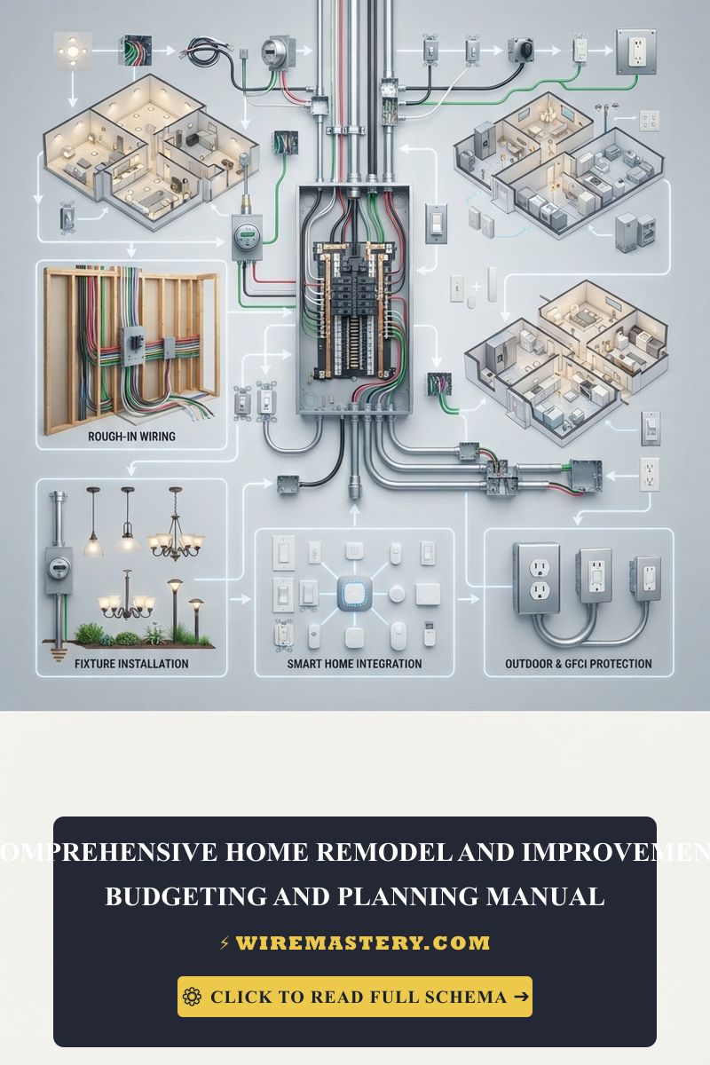
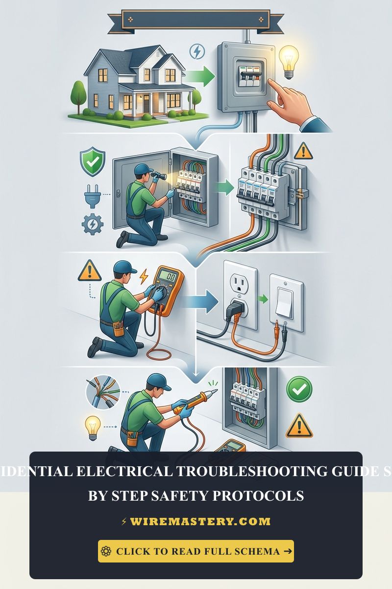
🛠️ Junction Resistance Maintenance Note: Look closely at the split-phase subpanel layouts and device assets displayed across our master troubleshooting portfolios. Notice that a high voltage drop reading at the furthest outlet does not automatically mean you have to rip out the entire wire line. First, execute the same load test at the intermediate boxes moving closer to the main panel. If the voltage drop disappears at Box 2 but explodes at Box 3, you have isolated the exact loose wire nut splice connecting those two nodes, allowing a localized repair loop.
Step-by-Step Restoration Manual for High-Resistance Connections
1. Removing Oxidized Copper Tips and Carbon Soot Layers
- Navigate to your property’s primary breaker panel and toggle the circuit breaker feeding the compromised branch to the absolute “OFF” position. Install your padlock clamp lockout device over the handle to secure the line.
- Open the localized junction enclosure and back out the device yoke. Use your non-contact tester to verify a true 0V AC state across all lines.
- Unwind the loose or charred wire nuts. If the solid copper tips display a dulled green oxide coating or a blackened carbon crust from progressive micro-arcing, you must cut the copper back.
- Use your high-leverage linesman pliers to shear away the damaged copper shank completely until reaching clean, ductile, shiny pink-colored copper cores.
2. Fabricating a Low-Impedance Pigtail Splice
- Strip exactly 3/4 inch of fresh insulation off your clean conductor ends using your precision wire strippers.
- Hold the raw copper ends perfectly side-by-side using the jaws of your linesman pliers. Twist the pliers clockwise firmly to mechanically twist the solid copper conductors around each other in a clean, uniform mechanical helix pattern.
- Cap the twisted connection with a brand-new, premium UL-listed twist-on wire nut. Twist the connector clockwise until the internal steel spring bites into the copper cores, clamping the assembly under permanent mechanical tension. Re-seat the device and torque the side screws tightly to eliminate progressive voltage sags.
National Electrical Code Branch Sizing Integrity
Adhering to strict construction regulations protects your property value, ensures full insurance compliance, and shields your family against high-amperage electrical hazards. The National Electrical Code strictly regulates residential branch circuit sizing, overcurrent protections, and continuous load factors under Sub-sections of NEC Article 210 (Branch Circuits) and Article 310 (Conductors for General Wiring):
- Continuous Load Amperage Headroom (NEC 210.20): Branch circuit overcurrent protection devices (circuit breakers) must be sized to handle 125% of the continuous load plus 100% of the non-continuous load. Siphoning maximum current capacities through thin lines forces thermal overloads, multiplying voltage drops.
- Conductor Ampacity Adjustments (NEC 310.15): If you route more than three current-carrying conductors through a single conduit track or tightly packed wall framing hole, you must derate the wire’s total allowable ampacity capacity, preventing cumulative thermal overheating inside wall cavities.
For the NFPA 70 provisions relevant to this guide on Residential Electrical Troubleshooting: Sizing Voltage Drops, consult the Official NFPA 70: National Electrical Code (NEC).
Conclusion
This guide covers executing open-circuit baseline matrices, calculating mathematical line attenuation equations, and isolating high-resistance wire nut dropouts using digital multimeters under active load conditions transforms chaotic electrical troubleshooting into a highly predictable science. By keeping branch voltage drops strictly within the 3% NEC legal boundary, cutting away oxidized copper conductor tips with high-leverage pliers, and respecting mandatory panel clearance frameworks, you construct an unshakeable, safe home grid environment. For final checks, complete panel breaker power isolation checks, deploy CAT III certified True RMS digital clamp meters, and execute every terminal step with safety-first precision.