Smart Lighting Control System Design: Installation Manual
Engineering a modern, automated electrical infrastructure or designing an advanced centralized smart lighting control system network demands a rigorous operational command of split-phase loading matrices, high-frequency digital bus signaling paths, and strict overcurrent protection limits. Within custom smart home architecture deployments, managing multiple ambient luminaire banks can no longer depend on simple standalone mechanical toggle slots or uninsulated wiring gutters. High-density properties integrating solid-state LED luminaire ballast drivers require synchronous, dimmable control networks that accept continuous data protocols—such as DALI loops, specialized KNX bus lines, or centralized wireless mesh grids—without inducing localized voltage drops. Executing these topologies without calculating active continuous load coefficients triggers progressive thermal insulation breakdown, causing micro-arcing faults hidden inside finished framing stud framing cavities.
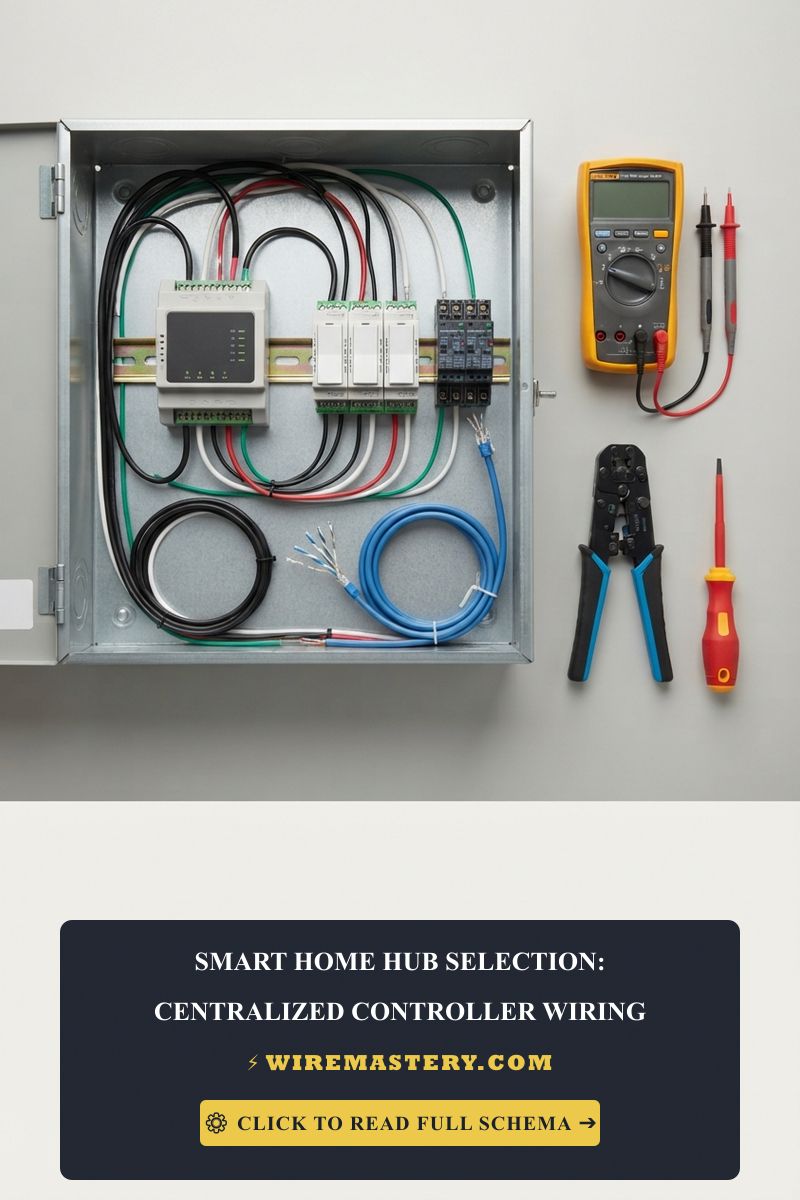
To prevent system performance degradation and maintain an unshakeable code-compliant data log, system integrators avoid unaligned electrical modifications. They pair their installation schematics directly with our verified centralized smart home hub DIN-rail wiring blueprints and follow our strict technical parameters for wiring single-pole and 3-way Lutron dimmer switch networks safely.
This systems manual details the precise mathematical equations behind ballast inrush current calculations, low-voltage control wire multiplexing, and professional on-site diagnostic metrology toolkits.
Core Smart Lighting Engineering Parameters
Before feeding multi-conductor cable coils into liquid-tight conduits or landing continuous phase wire loops onto smart dimmer module terminals, decode these essential thresholds:
- The LED Electronic Ballast Inrush Multiplier: Solid-state LED drivers do not behave as pure resistive heating loads under initial initialization phases. When an automated controller closes its contact pads to engage an LED array, internal smoothing input capacitors draw an instantaneous, transient inrush current spike that can exceed 100 times the nominal running current nameplate ratings for a microsecond fraction. Bypassing this spike when sizing relay switches will instantly weld the contact pads together, freezing the light circuit permanently “ON.”
- The 80% Continuous Protection Ceiling (NEC 210.20): Because an automated home lighting control system typically runs uninterrupted for windows exceeding 3 hours or more under nighttime operational profiles, the circuit is classified as a continuous load. Branch circuit conductors and supplying single-pole subpanel circuit breakers must be sized so that the maximum continuous current draw never exceeds 80% of the nominal branch ampacity rating, ensuring ample thermal ventilation headroom inside panel board gutters.
- The Multi-Point Dimming Control Separation: To secure uniform safety compliance across high-density multi-gang wall boxes, low-voltage digital signal communication wires (Class 2 circuits under NEC 725 rules) must maintain a continuous physical separation barrier from all unshielded 120V/240V building line potential wires entering the same electrical box enclosure.
Technical Materials & High-Impedance Automation Auditing Toolkit
Safely opening energized distribution enclosures and checking data bus line signal attenuation parameters requires specialized laboratory-grade testing instrumentation and ASTM-certified insulated hand tools:
| Automation Auditing Instrument | Primary Engineering Purpose & Trade Safety Verification Metric |
|---|---|
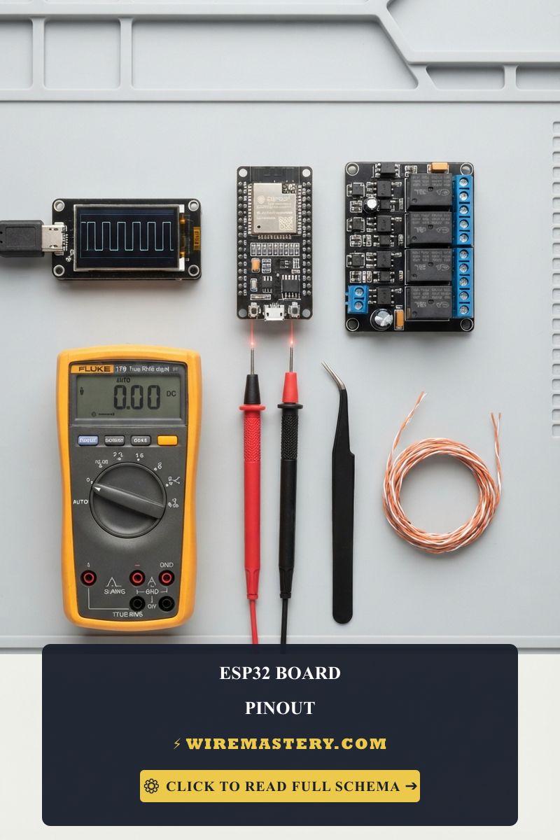
| True RMS CAT III Multimeter | Category CAT III 600V certified to accurately check voltage drops and relay path resistances. |
| Oscilloscope Signal Analyzer | Maps high-frequency digital square waves across DALI bus tracks to trace digital noise fields. |
| Non-Contact AC Proximity Wand | Proximity sensor calibrated to audibly guarantee 100% box de-energization before wire handling. |
| 1000V Insulated Torque Wrench | Calibration instrument to torque smart dimmer terminal blocks to exact manufacturer specs. |
| Class 00 Dielectric Rubber Gloves | High-density protective gloves rated to block up to 500V AC continuous contact tracks. |
Conductor Profiles & Continuous Overcurrent Boundaries (NEC Table 310.16)
Attempting to route heavy high-amperage automation loads over under-sized copper wire loops will instantly vaporize the insulation wraps. Installers match conductor diameters directly to the overcurrent protective ceiling enforced under NEC Article 310.16 parameters:
- 18 AWG Multi-Conductor Shielded Cable: The baseline specification required to wire localized low-voltage DALI or KNX digital data communication buses cleanly. It features an integrated aluminum foil shield layer to drain parasitic ambient electronic noise fields.
- 14 AWG Solid Copper Conductor (15-Amp Circuit Limit): Encased within standard white NM-B Romex protective sheaths. Sized exclusively to handle low-density automated ceiling fan paths and basic bedroom lighting loops.
- 12 AWG Solid Copper Conductor (20-Amp Circuit Limit): Encased within heavy-duty yellow NM-B Romex protective sheaths. The modern contractor infrastructure standard designed to safely sustain continuous current draws across custom smart home kitchen islands, automated master bathrooms, and external landscape lighting hubs.
Technical Phase 2: Centralized System Termination & Inrush Current Suppression
To implement a code-compliant smart lighting architecture, a systems engineer must look past basic wireless pairing sequences to focus strictly on physical wire terminations and the mechanical mitigation of electronic inrush loads.
1. Step-by-Step Field Blueprint: Wiring an Eight-Channel Smart Dimmer Module
To secure a multi-circuit centralized dimming module inside a dedicated automation enclosure enclosure box, execute this rigid field trade sequence:
- De-Energize and Isolate Power Loops: Navigate to your property’s primary distribution panel board center. Identify and disengage the dedicated circuit breaker toggle supplying power to the target room box enclosure. Install your padlock lockout safety tagout clamps over the switch. Confirm an absolute 0V parameters state across all side terminal blocks using your digital multimeter before wire handling.
- Mounting and Structural Space Allocations: Clip the smart dimming module securely onto the internal enclosure panel DIN rail track. Ensure you leave at least 1 inch of open air space on both sides of the plastic device chassis to provide adequate ventilation headroom for the internal solid-state triac switching components.
- Terminating the High-Voltage Line Feeders: Route your #12 AWG solid copper wire lines into the main power terminal ports. Twist your stranded wire filaments clockwise into clean hooks if using screw plates. Connect your continuous Line Hot wire (Black) straight into the terminal port stamped LINE IN, and land your Grounded Neutral (White) onto the shared neutral bus bar. Torque all screw plates to exact manufacturer specs using your calibrated screwdriver to eliminate seasonal heat expansion loose play faults.
- Wiring the Low-Voltage Control Signal Bus: Route your 18 AWG shielded data bus lines through separate low-voltage knockout apertures. Insert the red and black communication pairs directly into the terminal blocks stamped BUS + and BUS -. Ensure you fold the uninsulated aluminum foil shielding layer back and bond it straight onto the primary cabinet grounding lug block to drain parasitic ambient electronic noise fields cleanly to earth.
2. Suppressing Ballast Capacitor Arcs with Inrush Current Limiters (ICL)
When multiple high-performance LED luminaire ballast drivers initialize concurrently, their combined input capacitance generates a massive current spike that pits mechanical contacts.
- The Technical Remedy: Systems engineers mandate wiring a certified NTC (Negative Temperature Coefficient) Inrush Current Limiter (ICL) module in series directly along the switched hot output leg wire. The ICL presents a high initial resistance path that chokes the microsecond capacitor current surge, dropping thermal loading safely down to nominal operating levels before its core warms up and drops resistance to near-zero margins, saving your smart relays from failure.
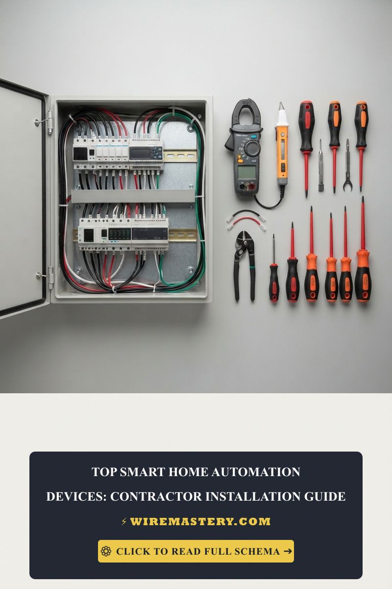
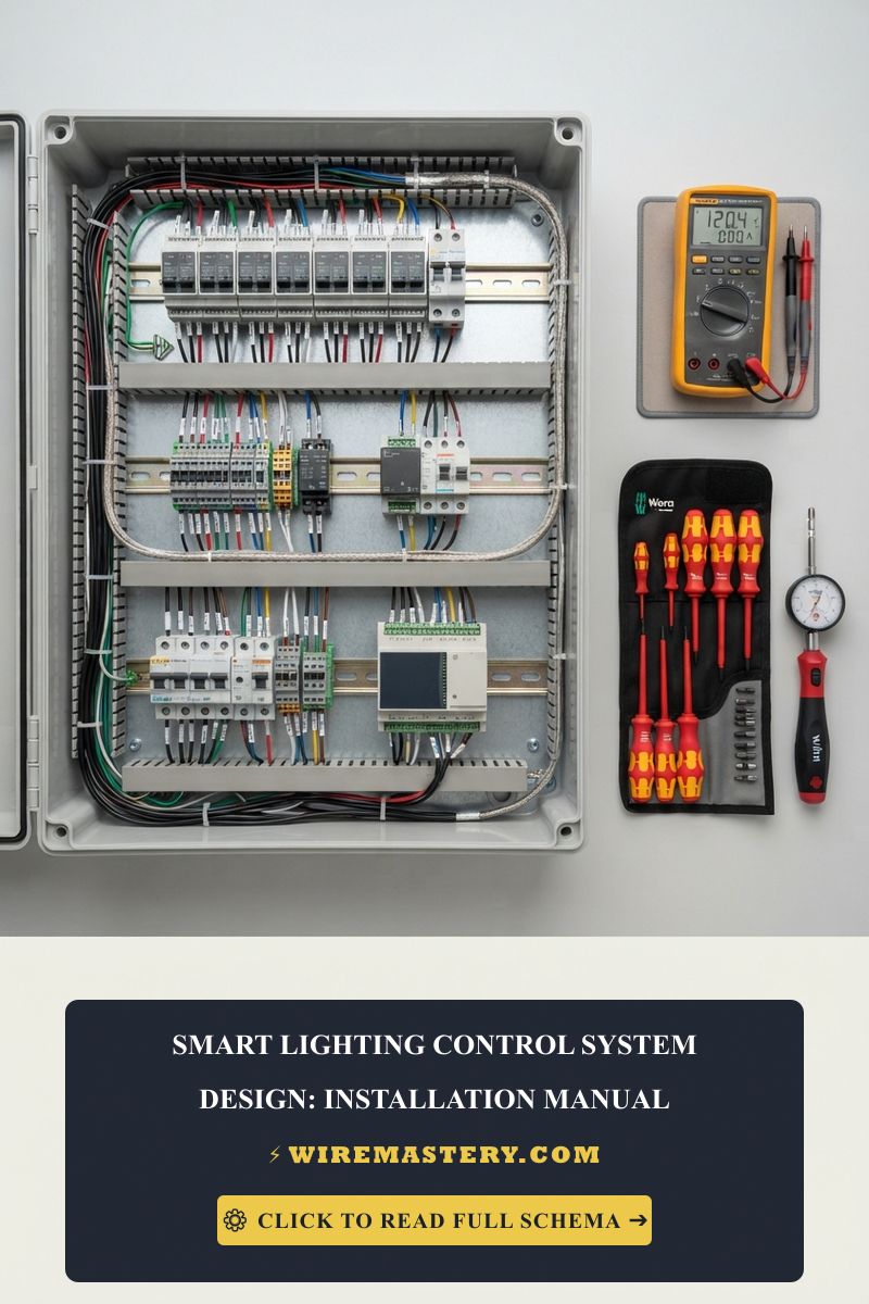
🛠️ The Box Fill Volume Safety Divider Note: Look closely at the multi-circuit panel board blueprints displayed across our modern home automation manuals. Notice that modern remodeling projects integrate thick, solid-state smart dimmer modules that house internal Wi-Fi radios and thermal heat sinks. Under the strict mandates of NEC 314.16(B), these bulky yokes require a double conductor volume deduction based on the supplying wire size. Always force your estimating team to budget for deep 22-cubic-inch thermoplastic or metallic box enclosures rather than standard shallow economy boxes, fully preventing wire insulation pinching faults during the final device seating phase.
Troubleshooting Smart Lighting Overloads & Communication Faults
- The Connected LED Fixtures Glow Faintly or Strobe Repeatedly When OFF: This operational failure confirms a parasitic voltage leakage or a missing capacitance bypass fault. Solid-state smart switch modules pass a tiny trickle of standby current through the switched hot return leg to power their internal logic microchips when the relay is disengaged. This trickle charges the input capacitors of low-wattage LED drivers, forcing a continuous discharge cycle. Install a parallel capacitor block directly across the luminaire load wire connections to siphon the leakage current safely past the LED chip.
- The Digital Data Bus Drops Communication Packages Automatically Under Load: An absolute indicator of Harmonic Noise Tracking caused by inadequate conduit routing separation. Your low-voltage 18 AWG signaling lines were packed inside the same metallic conduit raceway or pulled through the same framing stud holes parallel to unshielded 240V HVAC or water heater lines, violating NEC Article 800 guidelines. The intense fluctuating magnetic fields from high-power line current loops cross-talk into the data lines, scrambling digital square waves. Re-route data tracks using independent shielded conduit paths.
- The Centralized Automation Controller Module Emits an Acrid Smell and Trips Out: This symptom confirms a welded contact pad fault caused by an un-suppressed inrush surge loop. If multiple electronic drivers initialized simultaneously without an integrated ICL safety module, the microsecond current arc melted the internal metallic relay plating, welding the pads into a continuous closed short circuit. Replace the damaged dimming module and restructure your circuit counts to respect overcurrent limitations.
National Electrical Code Automation Panel Regulations
Adhering to strict national structural regulations protects your automated property investment from fire hazards, maintains full property insurance validity, and ensures complete safety compliance. Automated lighting configurations and distribution enclosures are heavily cross-regulated under NEC Article 404 (Switches) and Article 314:
- Mandatory Equipment Grounding Rules (NEC 404.9): All automated dimming modules, solid-state electronic switches, and smart home automation devices must be explicitly grounded to the equipment grounding conductor rail. The code mandates that even if you deploy a non-conductive plastic gang box enclosure, a dedicated bare copper or green insulated ground wire must land on the green hex grounding screw of every single device yoke strap, ensuring a stable path to ground to block chassis electrification hazards.
- Enclosure Workspace Clearance Zones (NEC 110.26): Centralized lighting control panel cabinets and railed subpanel gutters must maintain an absolute, un-obstructed physical working clear space envelope of at least 3 feet (36 inches) of front depth clearance and 30 inches of flat width clearance from the deadfront shield, extending from the floor up to a minimal height of 6.5 feet. Storing cargo, pallets, or building materials within this boundary zone is a critical federal code violation.
For the NFPA 70 provisions relevant to this guide on Smart Lighting Control System Design: Installation Manual, consult the Official NFPA 70: National Electrical Code (NEC).
Conclusion
This guide covers calculating electronic ballast inrush current multipliers, executing code-compliant serial integrations of Inrush Current Limiter (ICL) modules along switched hot paths, and isolating low-voltage digital data bus communication lines under strict NEC Article 404 safety separation rules transforms volatile smart lighting configurations into safe, highly predictable operations. By keeping branch conductor gauges fully aligned with NEC Table 310.16 overcurrent chart parameters, eliminating dangerous siphoning shortcuts across exposed metallic yokes, and respecting mandatory NEC workspace spatial envelopes, you construct an exceptionally resilient, safe home grid infrastructure. For final checks, complete panel breaker power isolation safety checkups before opening junction enclosures, deploy CAT III certified True RMS multimeters, and complete every mechanical terminal connection step with safety-first precision.